Arduino-Based MIDI Controller with Rotary Potentiometers and Analog Multiplexer
Circuit Documentation
Summary
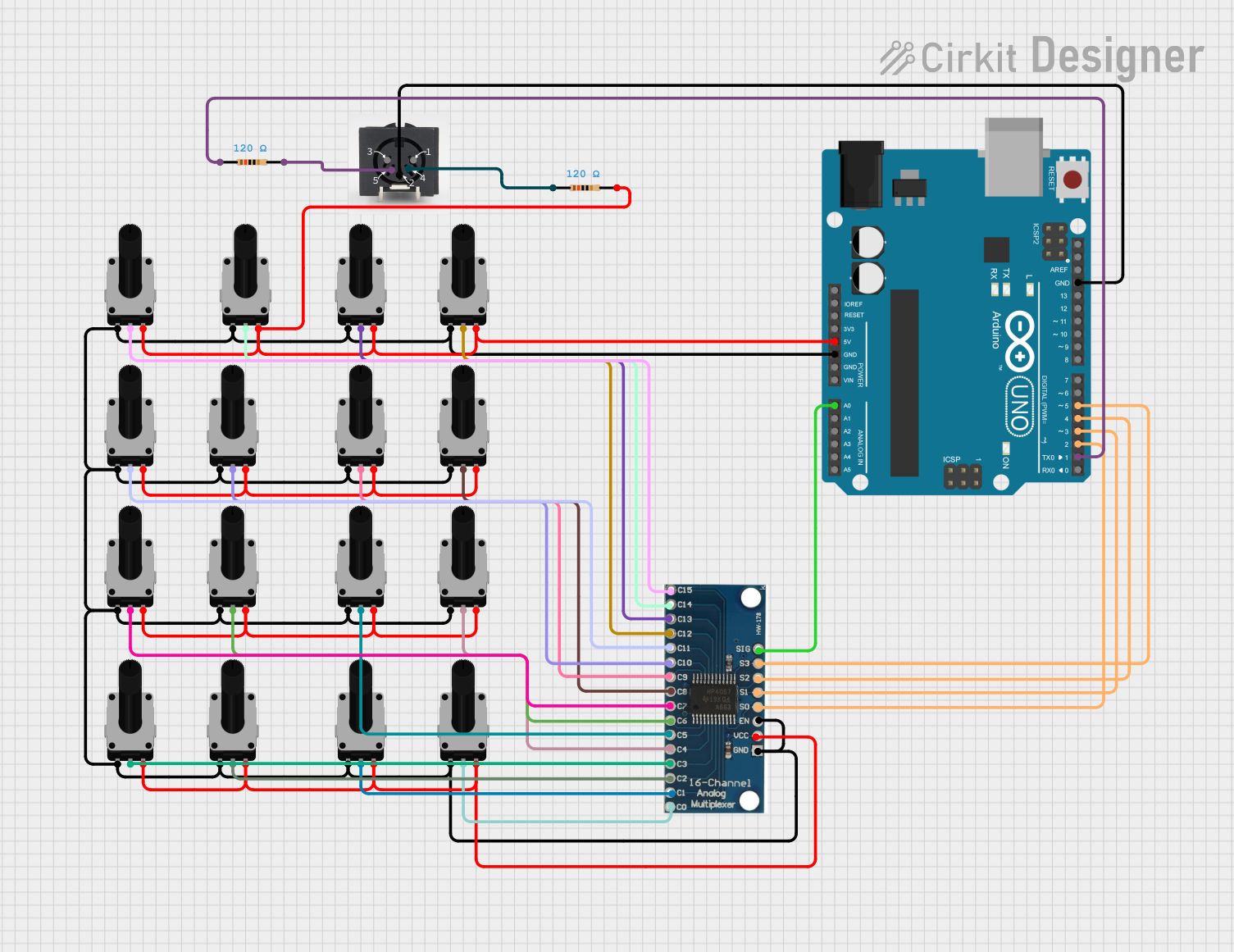
This circuit consists of multiple rotary potentiometers, a 16-channel analog multiplexer, an Arduino UNO, and a MIDI chassis connector. The potentiometers are used to provide variable resistance, which is read by the multiplexer and then processed by the Arduino. The Arduino also interfaces with the MIDI chassis connector to send or receive MIDI signals.
Component List
Rotary Potentiometer
- Description: A variable resistor with three terminals.
- Pins: leg1, wiper, leg2
- Properties:
- Resistance: 10,000 Ohms
Arduino UNO
- Description: A microcontroller board based on the ATmega328P.
- Pins: UNUSED, IOREF, Reset, 3.3V, 5V, GND, Vin, A0, A1, A2, A3, A4, A5, SCL, SDA, AREF, D13, D12, D11, D10, D9, D8, D7, D6, D5, D4, D3, D2, D1, D0
16 Channel Analog Multiplexer
- Description: A multiplexer that allows multiple analog signals to be routed to a single output.
- Pins: GND, VCC, EN, S0, S1, S2, S3, SIG, C0, C1, C2, C3, C4, C5, C6, C7, C8, C9, C10, C11, C12, C13, C14, C15
MIDI Chassis Connector
- Description: A connector for MIDI communication.
- Pins: 2, 4, 1, 3, 5
Resistor
- Description: A passive electrical component that implements electrical resistance.
- Pins: pin1, pin2
- Properties:
- Resistance: 120 Ohms
Wiring Details
Rotary Potentiometer
leg1 is connected to:
- leg1 of other rotary potentiometers
- GND of the Arduino UNO
- GND and EN of the 16-channel analog multiplexer
wiper is connected to:
- C14 of the 16-channel analog multiplexer
- C15 of the 16-channel analog multiplexer
- C13 of the 16-channel analog multiplexer
- C12 of the 16-channel analog multiplexer
- C11 of the 16-channel analog multiplexer
- C10 of the 16-channel analog multiplexer
- C9 of the 16-channel analog multiplexer
- C8 of the 16-channel analog multiplexer
- C7 of the 16-channel analog multiplexer
- C6 of the 16-channel analog multiplexer
- C5 of the 16-channel analog multiplexer
- C4 of the 16-channel analog multiplexer
- C3 of the 16-channel analog multiplexer
- C2 of the 16-channel analog multiplexer
- C1 of the 16-channel analog multiplexer
- C0 of the 16-channel analog multiplexer
leg2 is connected to:
- leg2 of other rotary potentiometers
- pin2 of a resistor
- 5V of the Arduino UNO
- VCC of the 16-channel analog multiplexer
Arduino UNO
GND is connected to:
- leg1 of rotary potentiometers
- pin 2 of the MIDI chassis connector
5V is connected to:
- leg2 of rotary potentiometers
A0 is connected to:
- SIG of the 16-channel analog multiplexer
D5 is connected to:
- S3 of the 16-channel analog multiplexer
D4 is connected to:
- S2 of the 16-channel analog multiplexer
D3 is connected to:
- S1 of the 16-channel analog multiplexer
D2 is connected to:
- S0 of the 16-channel analog multiplexer
D1 is connected to:
- pin1 of a resistor
16 Channel Analog Multiplexer
GND is connected to:
- leg1 of rotary potentiometers
- GND of the Arduino UNO
VCC is connected to:
- leg2 of rotary potentiometers
EN is connected to:
- leg1 of rotary potentiometers
S0 is connected to:
- D2 of the Arduino UNO
S1 is connected to:
- D3 of the Arduino UNO
S2 is connected to:
- D4 of the Arduino UNO
S3 is connected to:
- D5 of the Arduino UNO
SIG is connected to:
- A0 of the Arduino UNO
C0 to C15 are connected to:
- wiper of rotary potentiometers
MIDI Chassis Connector
Pin 2 is connected to:
- GND of the Arduino UNO
Pin 4 is connected to:
- pin1 of a resistor
Pin 5 is connected to:
- pin2 of a resistor
Resistor
pin1 is connected to:
- D1 of the Arduino UNO
- pin 4 of the MIDI chassis connector
pin2 is connected to:
- leg2 of rotary potentiometers
- pin 5 of the MIDI chassis connector
Documented Code
Arduino UNO Code (sketch.ino)
void setup() {
  // put your setup code here, to run once:

}

void loop() {
  // put your main code here, to run repeatedly:

}
Additional Documentation (documentation.txt)