
Arduino Mega 2560-Based Safety Monitoring and Control System with Temperature Sensor and Relay Module
View and Edit Project In Cirkit Designer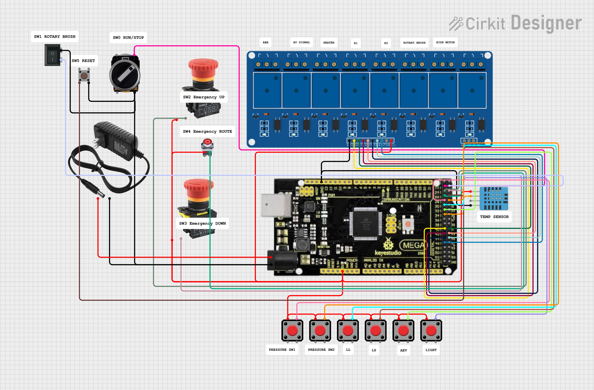
Circuit Documentation
Summary
This circuit is designed around an Arduino Mega 2560 R3 microcontroller. It integrates various input devices such as pushbuttons, emergency stop buttons, a 3-position switch, and a DHT11 humidity and temperature sensor. The circuit also includes a 5V 8-channel relay module for controlling external devices. The system is powered by an 8V power supply and includes safety mechanisms to stop operations in case of emergency conditions.
Component List
Mega 2560 R3
- Description: Arduino Mega 2560 R3 microcontroller board.
- Pins: ICSP port GND, ICSP port Reset, ICSP port MOSI, ICSP port SCK, ICSP port +VCC, ICSP port MISO, SCL, SDA, AREF, GND, D13 (PWM), D12 (PWM), D11 (PWM), D10 (PWM), D9 (PWM), D8 (PWM), D7 (PWM), D6 (PWM), D5 (PWM), D4 (PWM), D3 (PWM), D2 (PWM), D1 (TX0), D0 (RX0), D14 (TX3), D15 (RX3), D16 (TX2), D17 (RX2), D18 (TX1), D19 (RX1), D20 (SDA), D21 (SCL), + 5VCC, D22, D23, D24, D25, D26, D27, D28, D29, D30, D31, D32, D33, D34, D35, D36, D37, D38, D39, D40, D41, D42, D43, D44, D45, D46, D47, D48, D49, D50, D51, D52, D53, NC, IOREF, Reset, +3V3, +VCC IN, A0, A1, A2, A3, A4, A5, A6, A7, A8, A9, A10, A11, A12, A13, A14, A15, USB port.
DHT11 Humidity and Temperature Sensor
- Description: Sensor for measuring humidity and temperature.
- Pins: VDD, DATA, NULL, GND.
5V 8 Channel Relay Module
- Description: Relay module for controlling external devices.
- Pins: NC, COM, NO, GND, VCC, JD-VCC, IN8, IN7, IN6, IN5, IN4, IN3, IN2, IN1.
Emergency STOP
- Description: Emergency stop button.
- Pins: NC.
Pushbutton STOP
- Description: Pushbutton for stopping operations.
- Pins: NC, NO.
8V Power Supply
- Description: Power supply providing 8V.
- Pins: +, -.
3 Position Switch
- Description: Switch with three positions.
- Pins: 23, 11, 24, 12.
Pushbutton
- Description: General-purpose pushbutton.
- Pins: Pin 3 (out), Pin 4 (out), Pin 1 (in), Pin 2 (in).
Rocker Switch (SPST)
- Description: Single-pole single-throw rocker switch.
- Pins: 1, 2.
Wiring Details
Mega 2560 R3
GND connected to:
- DHT11 Humidity and Temperature Sensor (GND)
- 5V 8 Channel Relay Module (GND)
D22 connected to:
- 3 Position Switch (11)
D23 connected to:
- Rocker Switch (SPST) (2)
D24 connected to:
- Emergency STOP (NC)
D25 connected to:
- Emergency STOP (NC)
D26 connected to:
- Pushbutton STOP (NC)
D27 connected to:
- Pushbutton (Pin 2 (in))
D28 connected to:
- Pushbutton (Pin 4)
D29 connected to:
- Pushbutton (Pin 4)
D30 connected to:
- Pushbutton (Pin 4)
D31 connected to:
- Pushbutton (Pin 4)
D32 connected to:
- Pushbutton (Pin 4)
D33 connected to:
- Pushbutton (Pin 4)
D34 connected to:
- DHT11 Humidity and Temperature Sensor (DATA)
D40 connected to:
- 5V 8 Channel Relay Module (IN1)
D41 connected to:
- 5V 8 Channel Relay Module (IN2)
D42 connected to:
- 5V 8 Channel Relay Module (IN3)
D43 connected to:
- 5V 8 Channel Relay Module (IN4)
D44 connected to:
- 5V 8 Channel Relay Module (IN5)
D45 connected to:
- 5V 8 Channel Relay Module (IN6)
D46 connected to:
- 5V 8 Channel Relay Module (IN7)
+ 5VCC connected to:
- Pushbutton (Pin 1)
- Emergency STOP (NC)
- Pushbutton STOP (NC)
- DHT11 Humidity and Temperature Sensor (VDD)
- 5V 8 Channel Relay Module (VCC)
- Pushbutton (Pin 1)
+VCC IN connected to:
- 8V Power Supply (+)
GND connected to:
- 3 Position Switch (12)
- Pushbutton (Pin 4 (out))
- Rocker Switch (SPST) (1)
- 8V Power Supply (-)
DHT11 Humidity and Temperature Sensor
GND connected to:
- Mega 2560 R3 (GND)
DATA connected to:
- Mega 2560 R3 (D34)
VDD connected to:
- Mega 2560 R3 (+ 5VCC)
5V 8 Channel Relay Module
GND connected to:
- Mega 2560 R3 (GND)
IN1 connected to:
- Mega 2560 R3 (D40)
IN2 connected to:
- Mega 2560 R3 (D41)
IN3 connected to:
- Mega 2560 R3 (D42)
IN4 connected to:
- Mega 2560 R3 (D43)
IN5 connected to:
- Mega 2560 R3 (D44)
IN6 connected to:
- Mega 2560 R3 (D45)
IN7 connected to:
- Mega 2560 R3 (D46)
VCC connected to:
- Mega 2560 R3 (+ 5VCC)
Emergency STOP
- NC connected to:
- Mega 2560 R3 (D24)
Pushbutton STOP
- NC connected to:
- Mega 2560 R3 (D26)
8V Power Supply
+ connected to:
- Mega 2560 R3 (+VCC IN)
- connected to:
- Mega 2560 R3 (GND)
3 Position Switch
11 connected to:
- Mega 2560 R3 (D22)
12 connected to:
- Mega 2560 R3 (GND)
Pushbutton
Pin 2 (in) connected to:
- Mega 2560 R3 (D27)
Pin 4 connected to:
- Mega 2560 R3 (D28)
- Mega 2560 R3 (D29)
- Mega 2560 R3 (D30)
- Mega 2560 R3 (D31)
- Mega 2560 R3 (D32)
- Mega 2560 R3 (D33)
Pin 1 connected to:
- Mega 2560 R3 (+ 5VCC)
Rocker Switch (SPST)
2 connected to:
- Mega 2560 R3 (D23)
1 connected to:
- Mega 2560 R3 (GND)
Code Documentation
#include <DHT.h>

// Pin Definitions
#define SW0 22
#define SW1 23
#define SW2 24
#define SW3 25
#define SW4 26
#define SW5 27
#define PS1 28
#define PS2 29
#define LL 30
#define LS 31
#define AEV 32
#define L1 33
#define DHTPIN 34
#define DHTTYPE DHT11

#define OUT0 40