ESP8266 NodeMCU RFID Access Control System with Feedback Indicators
Circuit Documentation
Summary of the Circuit
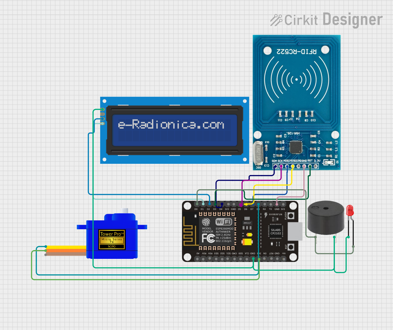
This circuit is designed to interface various components with an ESP8266 NodeMCU microcontroller. The components include a buzzer, a red two-pin LED, an RFID-RC522 module, a 16x2 LCD screen with I2C interface, and a Servomotor SG90. The ESP8266 NodeMCU serves as the central processing unit, controlling the peripherals through its GPIO pins. The circuit is likely intended for an RFID-based identification system with visual and auditory feedback, and the ability to drive a servo motor for physical interactions, such as unlocking a mechanism.
Component List
Buzzer
- Description: A simple piezoelectric buzzer for auditory feedback.
- Pins: PIN, GND
LED: Two Pin (red)
- Description: A red LED for visual indication.
- Pins: cathode, anode
ESP8266 NodeMCU
- Description: A Wi-Fi capable microcontroller with multiple GPIO pins.
- Pins: D0, D1, D2, D3, D4, 3V3, GND, D5, D6, D7, D8, RX, TX, A0, RSV, SD3, SD2, SD1, CMD, SD0, CLK, EN, RST, VIN
RFID-RC522
- Description: An RFID reader/writer module for contactless communication.
- Pins: VCC (3.3V), RST, GND, IRQ, MISO, MOSI, SCK, SDA
LCD screen 16x2 I2C
- Description: A 16x2 character LCD display with an I2C interface.
- Pins: SCL, SDA, VCC, GND
Servomotor SG90
- Description: A small and lightweight servo motor for precise angular movement.
- Pins: SIG, VCC, GND
Wiring Details
Buzzer
- PIN connected to ESP8266 NodeMCU D0
- GND connected to common ground
LED: Two Pin (red)
- anode connected to ESP8266 NodeMCU D0
- cathode connected to common ground
ESP8266 NodeMCU
- D0 connected to Buzzer PIN and LED anode
- D1 connected to LCD screen SCL
- D2 connected to LCD screen SDA
- D3 connected to RFID-RC522 RST
- D4 connected to RFID-RC522 SDA
- D5 connected to RFID-RC522 SCK
- D6 connected to RFID-RC522 MISO
- D7 connected to RFID-RC522 MOSI
- D8 connected to Servomotor SG90 SIG
- 3V3 connected to Servomotor SG90 VCC
- GND connected to common ground
RFID-RC522
- VCC (3.3V) not connected (requires connection to a 3.3V source)
- RST connected to ESP8266 NodeMCU D3
- GND connected to common ground
- IRQ not connected
- MISO connected to ESP8266 NodeMCU D6
- MOSI connected to ESP8266 NodeMCU D7
- SCK connected to ESP8266 NodeMCU D5
- SDA connected to ESP8266 NodeMCU D4
LCD screen 16x2 I2C
- SCL connected to ESP8266 NodeMCU D1
- SDA connected to ESP8266 NodeMCU D2
- VCC not connected (requires connection to a power source)
- GND connected to common ground
Servomotor SG90
- SIG connected to ESP8266 NodeMCU D8
- VCC connected to ESP8266 NodeMCU 3V3
- GND connected to common ground
Documented Code
No code has been provided for the microcontroller. The documentation of the code would typically include a description of the functionality, setup, and loop routines, along with any functions or libraries used to control the peripherals. Since no code is available, this section cannot be completed. It is recommended to provide the code for proper documentation and to ensure the circuit functions as intended.