
NodeMCU ESP8266 Based Smart Irrigation System with Environmental Sensing
View and Edit Project In Cirkit Designer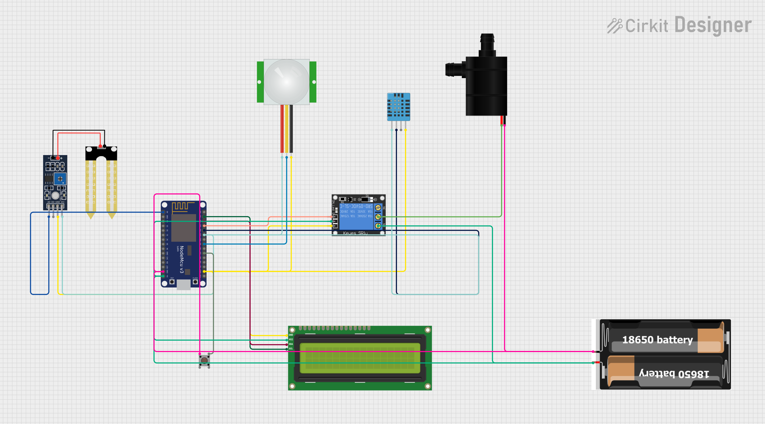
Circuit Documentation
Summary
This circuit integrates various sensors and actuators with a NodeMCU V3 ESP8266 microcontroller to create an interactive system capable of sensing environmental conditions and responding accordingly. The system includes a DHT11 humidity and temperature sensor, a PIR motion sensor, a YL-69 soil moisture sensor, and a 1-Channel Relay to control a water pump. User input is accepted through a pushbutton, and feedback is provided via an I2C LCD 16x2 screen. The power is supplied by a 2x 18650 battery pack. The circuit is designed for applications such as automated plant watering systems or environmental monitoring stations.
Component List
- NodeMCU V3 ESP8266: A microcontroller board based on the ESP8266 chip with WiFi capabilities. It has multiple digital and analog pins for interfacing with various sensors and actuators.
- DHT11 Humidity and Temperature Sensor: A sensor that measures ambient humidity and temperature.
- PIR Sensor: A motion sensor that detects the presence of humans or animals within its range.
- Humidity YL-69: A soil moisture sensor that measures the moisture level in the soil.
- 1-Channel Relay (5V 10A): An electromechanical switch that allows control of a high-power circuit by a low-power signal from the microcontroller.
- I2C LCD 16x2 Screen: A liquid crystal display that can show 16 characters per line on 2 lines, used for displaying information to the user.
- Pushbutton: A simple switch that allows user input when pressed.
- 2x 18650 Battery Pack: A power source consisting of two 18650 batteries.
- Water Pump: An actuator that pumps water when activated.
Wiring Details
NodeMCU V3 ESP8266
- A0: Connected to YL-69 A0 (Soil Moisture Sensor Analog Output)
- GND: Common ground with Pushbutton, Water Pump, 2x 18650 Battery Pack, and other components
- Vin: Connected to 2x 18650 Battery Pack VCC and I2C LCD Screen VCC (5V), 1-Channel Relay power and NO
- D0-D8, RX, TX: Various digital I/O pins used for interfacing with sensors and actuators
- 3V3: Power output connected to PIR Sensor VDD, DHT11 VDD, and YL-69 VCC
- D1 (SCL): Connected to I2C LCD Screen SCL
- D2 (SDA): Connected to I2C LCD Screen SDA
- D3: Connected to 1-Channel Relay signal
- D4: Connected to DHT11 DATA
- D5: Connected to PIR Sensor SIG
- D7: Connected to Pushbutton Pin 3 (out)
DHT11 Humidity and Temperature Sensor
- VDD: Connected to NodeMCU 3V3
- DATA: Connected to NodeMCU D4
- GND: Common ground
PIR Sensor
- VDD: Connected to NodeMCU 3V3
- SIG: Connected to NodeMCU D5
- GND: Common ground
Humidity YL-69
- A0: Connected to NodeMCU A0
- VCC: Connected to NodeMCU 3V3
- GND: Common ground
1-Channel Relay (5V 10A)
- NC: Normally closed contact (not used in this circuit)
- Signal: Connected to NodeMCU D3
- C: Connected to Water Pump VCC
- Power: Connected to 2x 18650 Battery Pack VCC
- NO: Normally open contact, connected to 2x 18650 Battery Pack VCC
- Ground: Common ground
I2C LCD 16x2 Screen
- SCL: Connected to NodeMCU D1
- SDA: Connected to NodeMCU D2
- VCC (5V): Connected to 2x 18650 Battery Pack VCC
- GND: Common ground
Pushbutton
- Pin 3 (out): Connected to NodeMCU D7
- Pin 1 (in): Common ground
2x 18650 Battery Pack
- VCC: Power supply to NodeMCU Vin, I2C LCD Screen VCC (5V), and 1-Channel Relay power and NO
- GND: Common ground
Water Pump
- VCC: Connected to 1-Channel Relay C
- GND: Common ground
Documented Code
No code was provided for the microcontroller. The system's functionality depends on the embedded code that would typically be written to read sensor data, process it, and control the actuators (LCD screen, relay for the water pump) based on the sensor inputs and user interaction through the pushbutton. The code would also handle WiFi connectivity features of the NodeMCU for potential IoT applications.