Arduino UNO Controlled Motion Detection and Wireless Communication System
Circuit Documentation
Summary
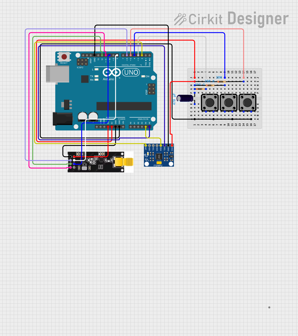
This circuit integrates a variety of components including sensors, communication modules, user input devices, and a microcontroller. The primary sensor used is the InvenSense MPU6050, a motion-tracking device with a 6-axis gyroscope and accelerometer. For wireless communication, the circuit employs an Nrf24l01 PA/LNA RF module. User inputs are captured through three tactile switch buttons. An Arduino UNO serves as the microcontroller to process data and control the circuit's behavior. The circuit also includes resistors and an electrolytic capacitor for stability and noise reduction.
Component List
Microcontroller
- Arduino UNO: A microcontroller board based on the ATmega328P, featuring digital and analog I/O pins.
Sensors
- InvenSense MPU6050: A 6-axis motion tracking device that combines a 3-axis gyroscope and a 3-axis accelerometer.
Communication Modules
- Nrf24l01 PA/LNA: A wireless communication module operating in the 2.4 GHz band, featuring an external antenna for extended range.
User Input Devices
- Tactile Switch Buttons - 12mm Square: Simple push-button switches for user input.
Passive Components
- Electrolytic Capacitor: A capacitor with a capacitance of 0.00047 Farads, used for power supply filtering.
- Resistors: Three resistors each with a resistance of 200 Ohms, likely used for pull-up or pull-down configurations.
Wiring Details
Arduino UNO
- 5V connected to the positive side of the Electrolytic Capacitor and VCC of the InvenSense MPU6050.
- 3.3V connected to VCC of the Nrf24l01 PA/LNA.
- GND connected to the negative side of the Electrolytic Capacitor, GND of the InvenSense MPU6050, and GND of the Nrf24l01 PA/LNA.
- A4 (SDA) connected to SDA of the InvenSense MPU6050.
- A5 (SCL) connected to SCL of the InvenSense MPU6050.
- D2 connected to INT of the InvenSense MPU6050.
- D3, D4, D5 connected to one side of each of the three 200 Ohm resistors, other sides connected to tactile switches.
- D6 connected to CE of the Nrf24l01 PA/LNA.
- D8 connected to CSN of the Nrf24l01 PA/LNA.
- D10 connected to MOSI of the Nrf24l01 PA/LNA.
- D11 connected to MISO of the Nrf24l01 PA/LNA.
- D12 connected to SCK of the Nrf24l01 PA/LNA.
InvenSense MPU6050
- VCC connected to 5V of the Arduino UNO.
- GND connected to GND of the Arduino UNO.
- SCL connected to A5 (SCL) of the Arduino UNO.
- SDA connected to A4 (SDA) of the Arduino UNO.
- INT connected to D2 of the Arduino UNO.
Nrf24l01 PA/LNA
- VCC connected to 3.3V of the Arduino UNO.
- GND connected to GND of the Arduino UNO.
- CE connected to D6 of the Arduino UNO.
- CSN connected to D8 of the Arduino UNO.
- SCK connected to D12 of the Arduino UNO.
- MOSI connected to D10 of the Arduino UNO.
- MISO connected to D11 of the Arduino UNO.
Tactile Switch Buttons - 12mm Square
- All switches have one pin connected to GND of the Arduino UNO and another pin connected through a 200 Ohm resistor to digital pins D3, D4, and D5 of the Arduino UNO respectively.
Electrolytic Capacitor
- + connected to 5V of the Arduino UNO.
- - connected to GND of the Arduino UNO.
Resistors (200 Ohms)
- One side connected to digital pins D3, D4, and D5 of the Arduino UNO, other sides connected to tactile switches.
Documented Code
The code for the Arduino UNO is written in C++ and utilizes several libraries to manage the MPU6050 sensor and the Nrf24l01 communication module. The code is structured to initialize the sensor and communication module, read the sensor data, process the data to calculate angles, and send commands based on button inputs and sensor readings.
The code begins with including necessary libraries and defining constants and variables for the MPU6050 registers, angles, button states, and radio communication. The setup() function initializes serial communication, the radio module, and the MPU6050 sensor, and calibrates the sensor. The loop() function reads the sensor values, calculates angles, checks button states, and sends commands via the radio module based on the processed sensor data and button states.
The code also contains functions for reading and writing to the MPU6050 registers, as well as utility functions for setting and getting the last read angles.
Due to the length and complexity of the code, it is not included in its entirety in this document. However, the code is well-structured and contains comments explaining the functionality of each section, which aids in understanding the flow and purpose of the program.