Cirkit Designer
Your all-in-one circuit design IDE
Home /
Project Documentation
Arduino UNO with NRF24L01 Wireless Communication Module
Circuit Documentation
Summary of the Circuit
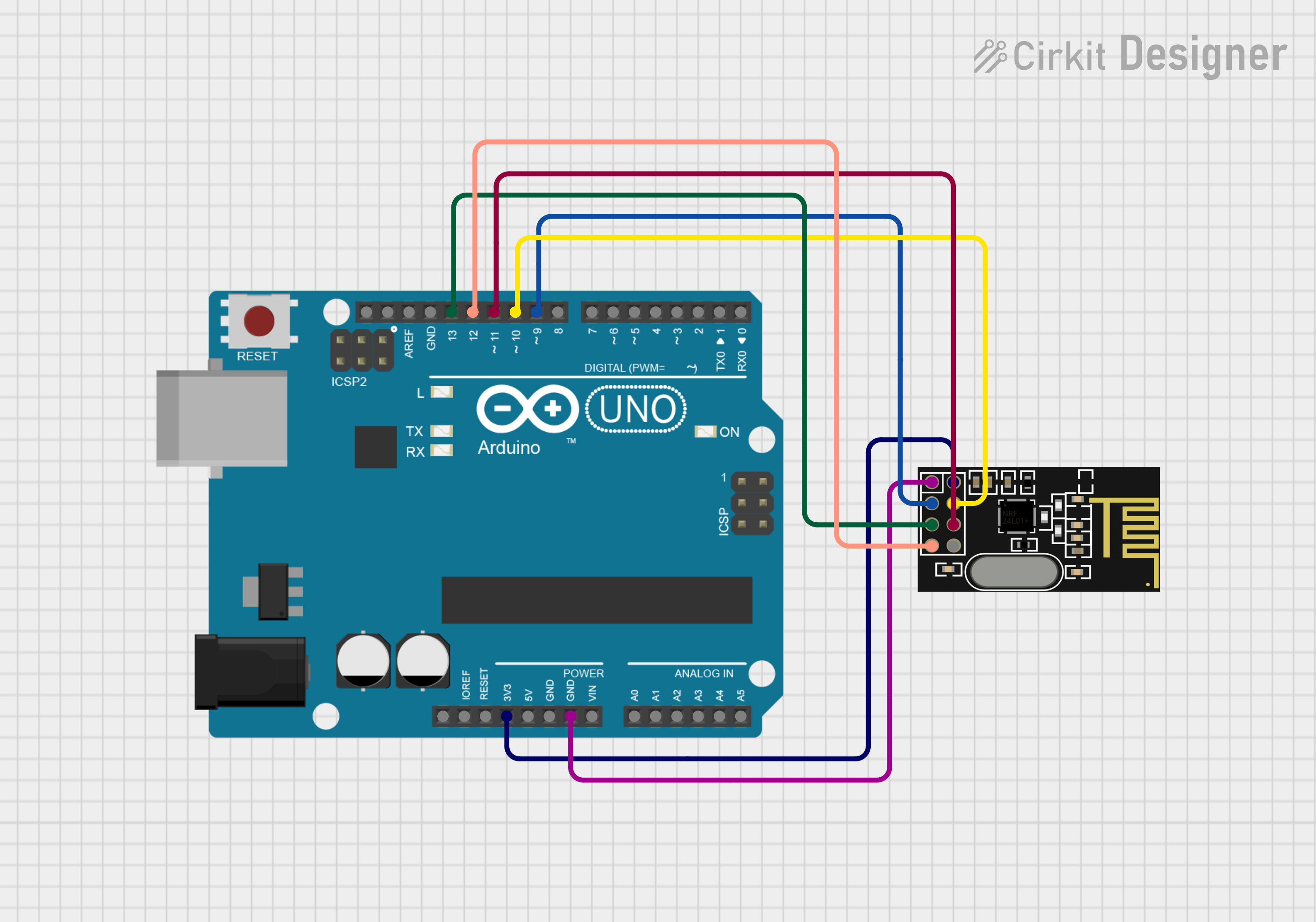
This circuit integrates an Arduino UNO microcontroller board with an NRF24L01 wireless transceiver module. The Arduino UNO serves as the central processing unit, controlling the operations of the NRF24L01 module, which enables wireless communication capabilities. The connections between the Arduino UNO and the NRF24L01 include power supply lines, ground, and SPI (Serial Peripheral Interface) communication lines.
Component List
Arduino UNO
- Description: A microcontroller board based on the ATmega328P.
- Pins: UNUSED, IOREF, Reset, 3.3V, 5V, GND, Vin, A0-A5, SCL, SDA, AREF, D0-D13.
- Purpose: Acts as the main controller for the circuit, executing the embedded code and interfacing with the NRF24L01 module.
NRF24L01
- Description: A 2.4GHz wireless transceiver module.
- Pins: IRQ (not used), MOSI, CSN, VCC (3V), GND, CE, SCK, MISO.
- Purpose: Provides wireless communication capabilities to the circuit.
Wiring Details
Arduino UNO
- 3.3V connected to NRF24L01 VCC (3V)
- GND connected to NRF24L01 GND
- D13 (SCK) connected to NRF24L01 SCK
- D12 (MISO) connected to NRF24L01 MISO
- D11 (MOSI) connected to NRF24L01 MOSI
- D10 (CSN) connected to NRF24L01 CSN
- D9 (CE) connected to NRF24L01 CE
NRF24L01
- VCC (3V) connected to Arduino UNO 3.3V
- GND connected to Arduino UNO GND
- SCK connected to Arduino UNO D13 (SCK)
- MISO connected to Arduino UNO D12 (MISO)
- MOSI connected to Arduino UNO D11 (MOSI)
- CSN connected to Arduino UNO D10 (CSN)
- CE connected to Arduino UNO D9 (CE)
Documented Code
Arduino UNO Code (sketch.ino)
void setup() {
  // put your setup code here, to run once:

}

void loop() {
  // put your main code here, to run repeatedly:

}
Additional Notes (documentation.txt)
No additional code documentation was provided.