Cirkit Designer
Your all-in-one circuit design IDE
Home /
Project Documentation
Arduino Nano Solar Power Monitoring System with ADS1115 and ACS712 Sensors
Circuit Documentation
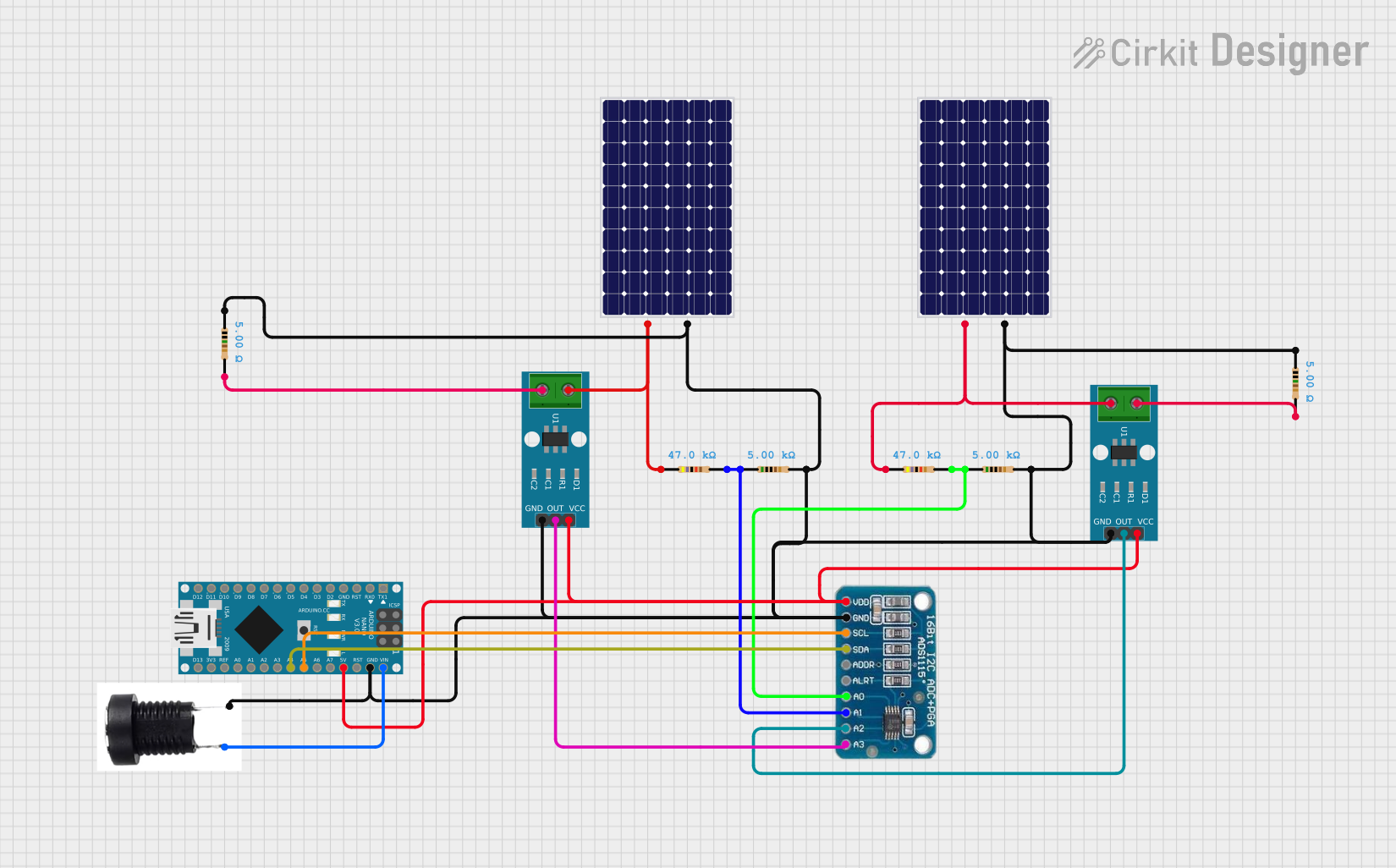
Summary
This circuit is designed to measure and monitor the voltage and current from two solar panels using an Arduino Nano, ADS1115 ADC, and ACS712 current sensors. The data is processed and displayed via the Arduino's serial monitor.
Component List
Arduino Nano
- Description: A small, complete, and breadboard-friendly board based on the ATmega328P.
- Pins: D1/TX, D0/RX, RESET, GND, D2, D3, D4, D5, D6, D7, D8, D9, D10, D11/MOSI, D12/MISO, VIN, 5V, A7, A6, A5, A4, A3, A2, A1, A0, AREF, 3V3, D13/SCK
ADS1115
- Description: A 16-bit ADC with four single-ended or two differential inputs.
- Pins: VDD, GND, SCL, SDA, ADDR, ALRT, A0, A1, A2, A3
ACS712 Current Sensor 5A 20A 30A
- Description: A current sensor that provides an analog voltage output proportional to the current passing through it.
- Pins: 1, 2, GND, OUT, VCC
Solar Panel
- Description: A device that converts light into electricity.
- Pins: +, -
Resistor (47k Ohms)
- Description: A resistor with a resistance of 47k Ohms.
- Pins: pin1, pin2
Resistor (5k Ohms)
- Description: A resistor with a resistance of 5k Ohms.
- Pins: pin1, pin2
DC Buchse
- Description: A DC power jack.
- Pins: Plus, Minus
Wiring Details
Arduino Nano
- VIN connected to Plus of DC Buchse
- GND connected to:
- GND of ACS712 Current Sensor 5A 20A 30A
- Minus of DC Buchse
- pin1 of Resistor (5k Ohms)
- pin2 of Resistor (5k Ohms)
- GND of ADS1115
- - of Solar Panel
- 5V connected to:
- VCC of ACS712 Current Sensor 5A 20A 30A
- VDD of ADS1115
- A5 connected to SCL of ADS1115
- A4 connected to SDA of ADS1115
ADS1115
- GND connected to GND of Arduino Nano
- VDD connected to 5V of Arduino Nano
- SCL connected to A5 of Arduino Nano
- SDA connected to A4 of Arduino Nano
- A0 connected to:
- pin2 of Resistor (47k Ohms)
- pin1 of Resistor (5k Ohms)
- A1 connected to:
- pin2 of Resistor (47k Ohms)
- pin1 of Resistor (5k Ohms)
- A2 connected to OUT of ACS712 Current Sensor 5A 20A 30A
- A3 connected to OUT of ACS712 Current Sensor 5A 20A 30A
ACS712 Current Sensor 5A 20A 30A
- GND connected to GND of Arduino Nano
- VCC connected to 5V of Arduino Nano
- OUT connected to:
- A2 of ADS1115
- A3 of ADS1115
- 1 connected to:
- pin2 of Resistor (47k Ohms)
- + of Solar Panel
- 2 connected to pin1 of Resistor (5k Ohms)
Solar Panel
- + connected to:
- 1 of ACS712 Current Sensor 5A 20A 30A
- pin1 of Resistor (47k Ohms)
- - connected to GND of Arduino Nano
Resistor (47k Ohms)
- pin1 connected to + of Solar Panel
- pin2 connected to:
- A0 of ADS1115
- pin1 of Resistor (5k Ohms)
Resistor (5k Ohms)
- pin1 connected to:
- pin2 of Resistor (47k Ohms)
- GND of Arduino Nano
- pin2 connected to:
- A1 of ADS1115
- pin1 of Resistor (47k Ohms)
DC Buchse
- Plus connected to VIN of Arduino Nano
- Minus connected to GND of Arduino Nano
Code Documentation
#include <Adafruit_ADS1X15.h>

Adafruit_ADS1115 ads;

const float R1 = 47000.0;                      // First resistor value in voltage divider (ohms)
const float R2 = 5000.0;                       // Second resistor value in voltage divider (ohms)
const float CURRENT_SENSOR_SENSITIVITY = 0.1;  //  0.1 for 20A Module
const float CURRENT_SENSOR_OFFSET = 2.5;       // Offset voltage for current sensor (V)
const float VOLTAGE_DIVIDER_RATIO = (R1 + R2) / R2;

void setup() {
  // put your setup code here, to run once:
  Serial.begin(9600);
  ads.setGain(GAIN_TWOTHIRDS);  // 2/3x gain +/- 6.144V  1 bit = 3mV      0.1875mV (default)

  if (!ads.begin()) {
    Serial.println("Failed to initialize ADS.");
    while (1)
      ;
  }
}

void loop() {
  int16_t adc0 = ads.readADC_SingleEnded(0);  // Old PV Voltage
  int16_t adc1 = ads.readADC_SingleEnded(1);  // New PV Voltage
  int16_t adc2 = ads.readADC_SingleEnded(2);  // Old PV Current
  int16_t adc3 = ads.readADC_SingleEnded(3);  // New PV Current
  // Read voltage sensor values
  float PV_V1 = ads.computeVolts(adc0) * VOLTAGE_DIVIDER_RATIO;
  float PV_V2 = ads.computeVolts(adc1) * VOLTAGE_DIVIDER_RATIO;
  // Read current sensor values
  float PV_C1 = (ads.computeVolts(adc2) - CURRENT_SENSOR_OFFSET) / CURRENT_SENSOR_SENSITIVITY;
  float PV_C2 = (ads.computeVolts(adc3) - CURRENT_SENSOR_OFFSET) / CURRENT_SENSOR_SENSITIVITY;

  // Calculate power only if readings are valid
  float PV_P1 =  PV_V1 * PV_C1 ;
  float PV_P2 =  PV_V2 * PV_C2 ;

  Serial.println("-----------------------------------------------------------");
  Serial.print("AIN0: ");
  Serial.print(adc0);
  Serial.print("\t");
  Serial.print("PV1 Voltage");
  Serial.println(PV_V1);
  Serial.print("AIN1: ");
  Serial.print(adc1);
  Serial.print("\t");
  Serial.print("PV2 Voltage:");
  Serial.println(PV_V2);
  Serial.print("AIN2: ");
  Serial.print(adc2);
  Serial.print("\t");
  Serial.print("PV1 Current:");
  Serial.println(PV_C1);
  Serial.print("AIN3: ");
  Serial.print(adc3);
  Serial.print("\t");
  Serial.print("PV2 Current:");
  Serial.println(PV_C2);
  Serial.print("PV1 Power:");
  Serial.println(PV_P1);
  Serial.print("PV2 Power:");
  Serial.println(PV_P2);
  delay(1000);
}
This code initializes the ADS1115 ADC and reads voltage and current values from the connected sensors. It then calculates the power generated by each solar panel and prints the results to the serial monitor.