
Arduino-Controlled Robotics Platform with IR and Ultrasonic Sensors
View and Edit Project In Cirkit Designer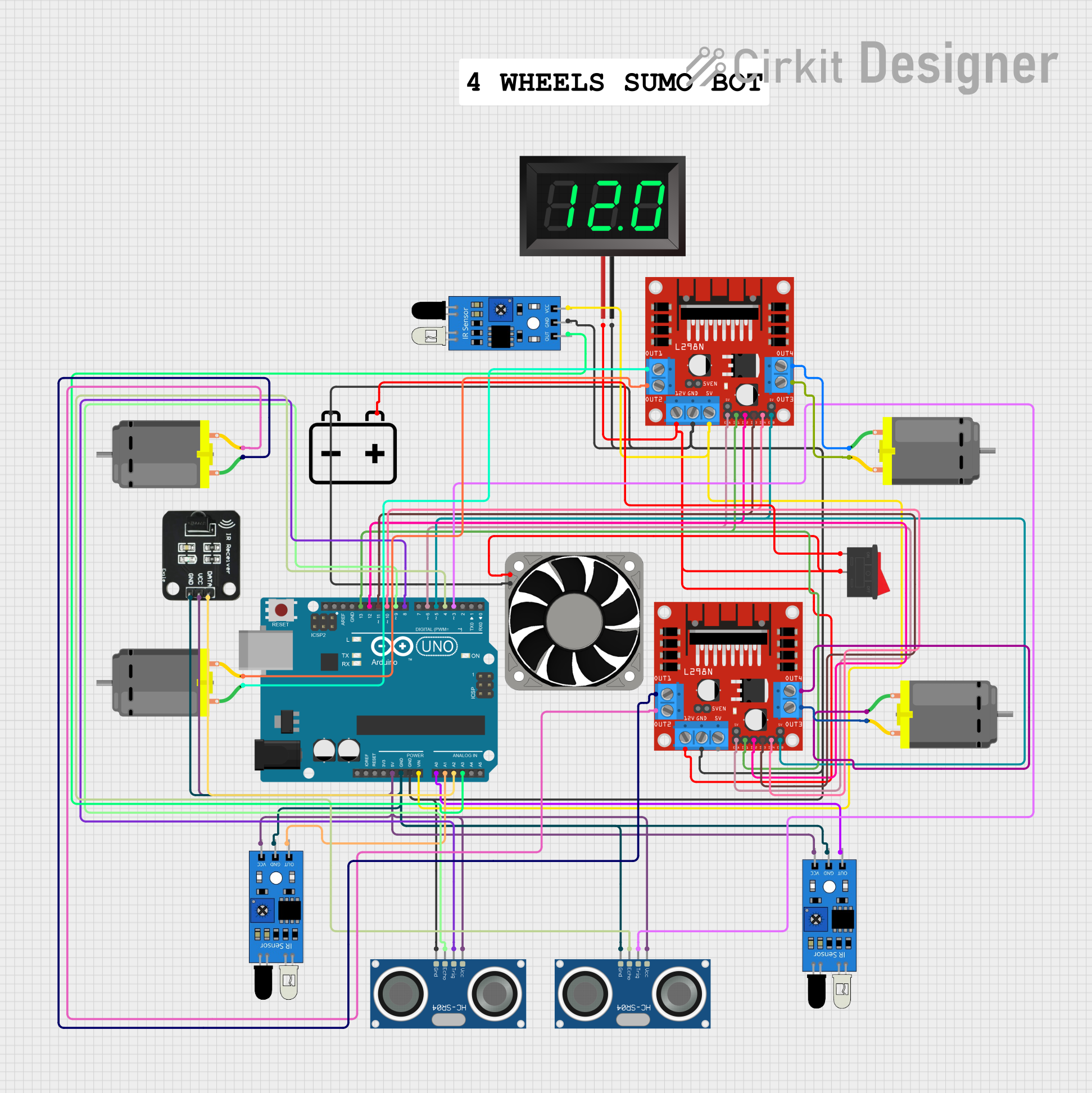
Circuit Documentation
Summary
This circuit is designed to control multiple DC motors using L298N motor drivers, with inputs from IR sensors and ultrasonic sensors. An Arduino UNO serves as the central microcontroller, interfacing with the sensors and motor drivers to manage the motors' speed and direction. The circuit also includes a 12V battery to power the motors and a 7-segment panel voltmeter for voltage display. A rocker switch is used to control the power supply to the circuit, and a 40mm 12V fan is included, possibly for cooling purposes.
Component List
Microcontroller
- Arduino UNO: A microcontroller board based on the ATmega328P, with a variety of digital and analog I/O pins.
Motor Drivers
- L298N DC Motor Driver: A high-power motor driver capable of driving up to two DC motors.
Sensors
- IR Sensor: Used to detect obstacles or perform simple communication via infrared signals.
- HC-SR04 Ultrasonic Sensor: Measures distance using ultrasonic waves.
- IR Receiver: Receives infrared signals and outputs the signal's data.
Actuators
- DC Motor: Converts electrical energy into mechanical motion.
Power Supply
- 12V Battery: Provides the power source for the motors and other components in the circuit.
Display
- 7-Segment Panel Voltmeter: Displays the voltage level of the power supply.
Cooling
- 40mm Fan 12V: Provides airflow for cooling components within the circuit.
Switch
- Rocker Switch: A simple on/off switch to control the power flow in the circuit.
Wiring Details
Arduino UNO
- GND: Connected to the ground of the battery, motor drivers, sensors, and IR receiver.
- Vin: Connected to the 5V output of the L298N motor driver.
- 5V: Powers the IR sensors, ultrasonic sensors, and IR receiver.
- D3, D4, D5, D6, D8, D9, D10, D11, D12, D13: Control signals for the motor drivers and trigger/echo pins for the ultrasonic sensors.
- A0, A1, A2, A3: Analog inputs connected to the output of the IR sensors and the data pin of the IR receiver.
L298N DC Motor Driver
- OUT1, OUT2, OUT3, OUT4: Connected to the terminals of the DC motors.
- 12V: Powered by the 12V battery through the rocker switch.
- GND: Common ground with the Arduino UNO and other components.
- 5V: Receives power from the Arduino UNO's Vin pin.
- ENA, ENB: Enable pins for the motor driver, controlled by the Arduino UNO.
- IN1, IN2, IN3, IN4: Input pins for motor direction control, connected to the Arduino UNO.
IR Sensor
- VCC: Powered by the 5V output from the Arduino UNO.
- GND: Common ground with the Arduino UNO.
- OUT: Output signal connected to the Arduino UNO's analog input pins.
HC-SR04 Ultrasonic Sensor
- VCC: Powered by the 5V output from the Arduino UNO.
- GND: Common ground with the Arduino UNO.
- TRIG: Trigger pin controlled by the Arduino UNO.
- ECHO: Echo pin connected to the Arduino UNO's digital input pins.
IR Receiver
- VCC: Powered by the 5V output from the Arduino UNO.
- GND: Common ground with the Arduino UNO.
- DATA: Data pin connected to the Arduino UNO's analog input pin.
DC Motor
- Pin 1, Pin 2: Connected to the output pins of the L298N motor drivers.
12V Battery
- +: Connected to the rocker switch and the 12V input of the motor drivers.
- -: Common ground with the circuit.
7-Segment Panel Voltmeter
- V+: Connected to the 12V battery.
- V-: Common ground with the circuit.
40mm Fan 12V
- +12V: Powered by the 12V battery.
- -12V: Common ground with the circuit.
Rocker Switch
- Pin 1: Connected to the positive terminal of the 12V battery.
- Pin 2: Provides controlled power to the motor drivers and the 7-segment panel voltmeter.
Documented Code
Arduino UNO Code (sketch.ino)
void setup() {
  // put your setup code here, to run once:

}

void loop() {
  // put your main code here, to run repeatedly:

}
Note: The provided code is a template and does not contain any functional instructions. It needs to be populated with the logic to control the motors based on sensor inputs and possibly to display the voltage on the voltmeter.