Cirkit Designer
Your all-in-one circuit design IDE
Home /
Project Documentation
Arduino UNO Bluetooth-Controlled 2-Wheel Drive Robot with Servo Motors
Circuit Documentation
Summary
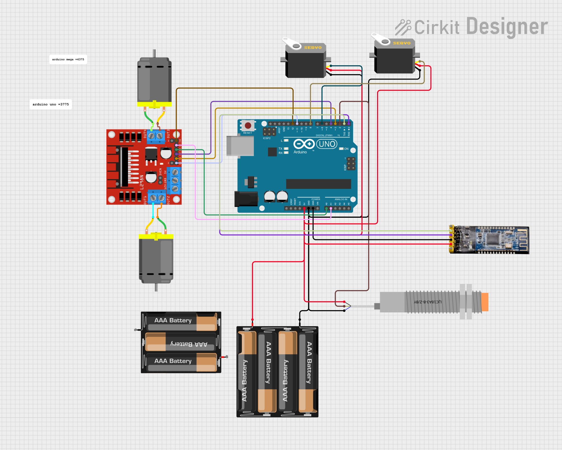
This document provides a detailed overview of a circuit designed to control a 2-wheel drive robot with two servos and communicate with the ArduinoBlue app via the HM-10 Bluetooth module. The robot can move forward, backward, and turn, while the servos can be controlled for additional functionalities. The circuit includes various components such as an Arduino UNO, DC motors, a motor driver, servos, a capacitive proximity sensor, a Bluetooth module, and battery mounts.
Component List
LJC18A3-B-Z/BY Capacitive Proximity Sensor
- Pins: VO (BLU), VI (BRN), SIG (BLK)
- Description: Detects the presence of nearby objects without physical contact.
DC Motor
- Pins: pin 1, pin 2
- Description: Converts electrical energy into mechanical motion.
4 x AAA Battery Mount
- Pins: -, +
- Description: Holds and connects four AAA batteries to power the circuit.
3xAA Battery
- Pins: VCC, GND
- Description: Provides power to the circuit.
L298N DC Motor Driver
- Pins: OUT1, OUT2, 12V, GND, 5V, OUT3, OUT4, 5V-ENA-JMP-I, 5V-ENA-JMP-O, +5V-J1, +5V-J2, ENA, IN1, IN2, IN3, IN4, ENB
- Description: Controls the speed and direction of DC motors.
Servo
- Pins: gnd, vcc, pulse
- Description: Provides precise control of angular position.
Arduino UNO
- Pins: UNUSED, IOREF, Reset, 3.3V, 5V, GND, Vin, A0, A1, A2, A3, A4, A5, SCL, SDA, AREF, D13, D12, D11, D10, D9, D8, D7, D6, D5, D4, D3, D2, D1, D0
- Description: Microcontroller board used for controlling the circuit.
Bluetooth module HM-10
- Pins: BRK, RX, TX, GND, VCC, State
- Description: Enables wireless communication between the robot and a smartphone app.
Wiring Details
LJC18A3-B-Z/BY Capacitive Proximity Sensor
- VO (BLU): Connected to GND of Arduino UNO and 4 x AAA Battery Mount.
- VI (BRN): Connected to D2 of Arduino UNO.
- SIG (BLK): Connected to 5V of Arduino UNO and + of 4 x AAA Battery Mount.
DC Motor 1
- pin 1: Connected to OUT4 of L298N DC Motor Driver.
- pin 2: Connected to OUT3 of L298N DC Motor Driver.
DC Motor 2
- pin 1: Connected to OUT2 of L298N DC Motor Driver.
- pin 2: Connected to OUT1 of L298N DC Motor Driver.
4 x AAA Battery Mount
- +: Connected to 5V of Arduino UNO, vcc of both Servos, SIG (BLK) of Capacitive Proximity Sensor, and VCC of Bluetooth module HM-10.
- -: Connected to GND of Arduino UNO, gnd of both Servos, and VO (BLU) of Capacitive Proximity Sensor.
3xAA Battery
- VCC: Not connected in the provided net list.
- GND: Not connected in the provided net list.
L298N DC Motor Driver
- IN1: Connected to D3 of Arduino UNO.
- IN2: Connected to D4 of Arduino UNO.
- IN3: Connected to A0 of Arduino UNO.
- IN4: Connected to A1 of Arduino UNO.
- ENA: Connected to D11 of Arduino UNO.
- ENB: Connected to D12 of Arduino UNO.
- OUT1: Connected to pin 2 of DC Motor 2.
- OUT2: Connected to pin 1 of DC Motor 2.
- OUT3: Connected to pin 2 of DC Motor 1.
- OUT4: Connected to pin 1 of DC Motor 1.
Servo 1
- gnd: Connected to GND of Arduino UNO and 4 x AAA Battery Mount.
- vcc: Connected to 5V of Arduino UNO and + of 4 x AAA Battery Mount.
- pulse: Connected to D6 of Arduino UNO.
Servo 2
- gnd: Connected to GND of Arduino UNO and 4 x AAA Battery Mount.
- vcc: Connected to 5V of Arduino UNO and + of 4 x AAA Battery Mount.
- pulse: Connected to D8 of Arduino UNO.
Arduino UNO
- 5V: Connected to + of 4 x AAA Battery Mount, vcc of both Servos, SIG (BLK) of Capacitive Proximity Sensor, and VCC of Bluetooth module HM-10.
- GND: Connected to - of 4 x AAA Battery Mount, gnd of both Servos, VO (BLU) of Capacitive Proximity Sensor, and GND of Bluetooth module HM-10.
- D2: Connected to VI (BRN) of Capacitive Proximity Sensor.
- D3: Connected to IN1 of L298N DC Motor Driver.
- D4: Connected to IN2 of L298N DC Motor Driver.
- D6: Connected to pulse of Servo 1.
- D8: Connected to pulse of Servo 2.
- D11: Connected to ENA of L298N DC Motor Driver.
- D12: Connected to ENB of L298N DC Motor Driver.
- A0: Connected to IN3 of L298N DC Motor Driver.
- A1: Connected to IN4 of L298N DC Motor Driver.
- D0: Connected to TX of Bluetooth module HM-10.
- D1: Connected to RX of Bluetooth module HM-10.
Bluetooth module HM-10
- VCC: Connected to 5V of Arduino UNO and + of 4 x AAA Battery Mount.
- GND: Connected to GND of Arduino UNO and - of 4 x AAA Battery Mount.
- RX: Connected to D1 of Arduino UNO.
- TX: Connected to D0 of Arduino UNO.
Documented Code
/*
 * This Arduino sketch controls a 2-wheel drive robot with 2 servos and
 * communicates with the ArduinoBlue app via the HM-10 Bluetooth module.
 * The robot can move forward, backward, and turn, while the servos can be
 * controlled for additional functionalities.
 */

#include <Servo.h>
#include <ArduinoBlue.h>

// Pin Assignments
const int motorPin1 = 3;
const int motorPin2 = 4;
const int motorPin3 = A0;
const int motorPin4 = A1;
const int enableA = 11;
const int enableB = 12;
const int servoPin1 = 6;
const int servoPin2 = 8;

// Bluetooth
const int btRx = 0;
const int btTx = 1;
ArduinoBlue phone(btRx, btTx);

// Servos
Servo servo1;
Servo servo2;

void setup() {
  // Setup motor control pins
  pinMode(motorPin1, OUTPUT);
  pinMode(motorPin2, OUTPUT);
  pinMode(motorPin3, OUTPUT);
  pinMode(motorPin4, OUTPUT);
  pinMode(enableA, OUTPUT);
  pinMode(enableB, OUTPUT);

  // Initialize servos
  servo1.attach(servoPin1);
  servo2.attach(servoPin2);

  // Set motor speed
  analogWrite(enableA, 255);  // Max speed for motor 1
  analogWrite(enableB, 255);  // Max speed for motor 2

  // Initialize Bluetooth
  phone.begin(9600);
}

void loop() {
  // Read Bluetooth commands
  char command = phone.getButton();

  switch (command) {
    case 'F':
      moveForward();
      break;
    case 'B':
      moveBackward();
      break;
    case 'L':
      turnLeft();
      break;
    case 'R':
      turnRight();
      break;
    case 'S':
      stopMotors();
      break;
    case '1':
      servo1.write(0);
      break;
    case '2':
      servo1.write(90);
      break;
    case '3':
      servo2.write(0);
      break;
    case '4':
      servo2.write(90);
      break;
    default:
      stopMotors();
      break;
  }
}

// Function to stop all motors
void stopMotors() {
  digitalWrite(motorPin1, LOW);
  digitalWrite(motorPin2, LOW);
  digitalWrite(motor