Cirkit Designer
Your all-in-one circuit design IDE
Home /
Project Documentation
Arduino UNO Controlled IR Sensor Array with Servo and I2C LCD Display
Circuit Documentation
Summary of the Circuit
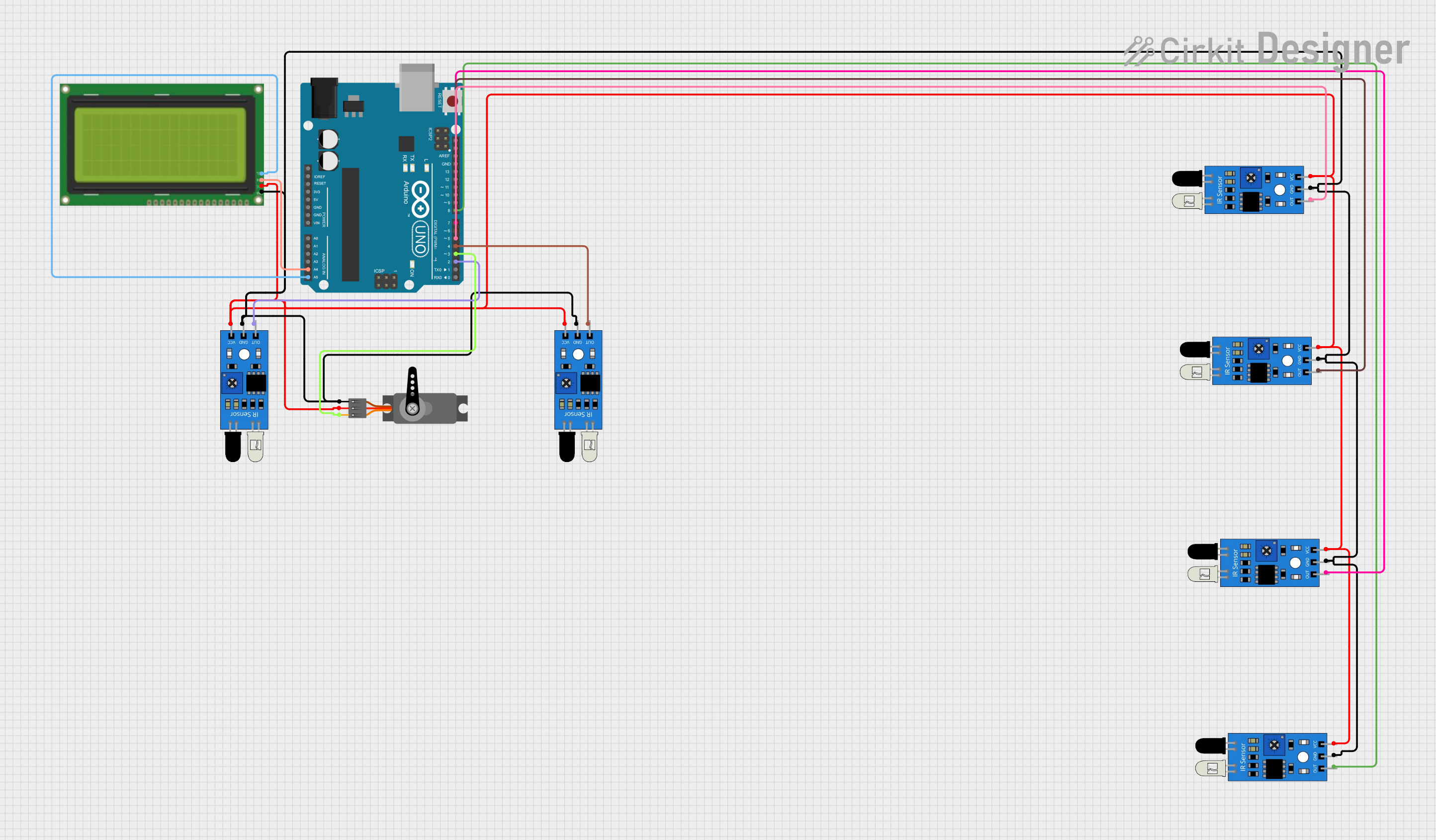
This circuit consists of an Arduino UNO microcontroller interfaced with multiple IR sensors, a servo motor, and an LCD display with an I2C interface. The IR sensors are used to detect the presence or absence of objects, while the servo motor is controlled by the Arduino UNO. The LCD display shows information or status messages. The Arduino UNO serves as the central processing unit, reading inputs from the IR sensors and controlling the servo motor accordingly. It also communicates with the LCD display via the I2C protocol.
Component List
Arduino UNO
- Microcontroller board based on the ATmega328P
- It has 14 digital input/output pins, 6 analog inputs, a 16 MHz quartz crystal, a USB connection, a power jack, an ICSP header, and a reset button.
IR Sensors
- Used for object detection
- Each sensor has three pins: out (signal), gnd (ground), and vcc (power).
Servo
- An actuator that can be precisely controlled for angular position
- It has three pins: GND (ground), VCC (power), and PWM (pulse-width modulation signal).
LCD 20x4 I2C
- A 20x4 character LCD display with an I2C interface
- It has four pins: GND (ground), 5V (power), SCA (I2C data), and SCL (I2C clock).
Wiring Details
Arduino UNO
- A4 (SDA) connected to LCD SCA
- A5 (SCL) connected to LCD SCL
- D2 to D8 connected to IR sensor outputs
- D3 connected to Servo PWM
IR Sensors
- Out pin connected to individual digital pins D2 to D8 on the Arduino UNO
- GND pins connected to common ground
- VCC pins connected to common 5V supply
Servo
- PWM pin connected to D3 on the Arduino UNO
- GND pin connected to common ground
- VCC pin connected to common 5V supply
LCD 20x4 I2C
- SCA pin connected to A4 on the Arduino UNO
- SCL pin connected to A5 on the Arduino UNO
- GND pin connected to common ground
- 5V pin connected to common 5V supply
Documented Code
Arduino UNO Code (sketch.ino)
void setup() {
  // put your setup code here, to run once:

}

void loop() {
  // put your main code here, to run repeatedly:

}
Additional Notes
- The provided code is a template and does not contain any functional code for the operation of the circuit.
- The actual implementation should initialize the I2C interface for the LCD, configure the servo motor, and set up the IR sensors for input.
- The loop function should contain the logic for reading the IR sensor states, controlling the servo, and updating the display on the LCD.