Cirkit Designer
Your all-in-one circuit design IDE
Home /
Project Documentation
Battery-Powered LED Circuit with Pushbutton Control
Circuit Documentation
Summary
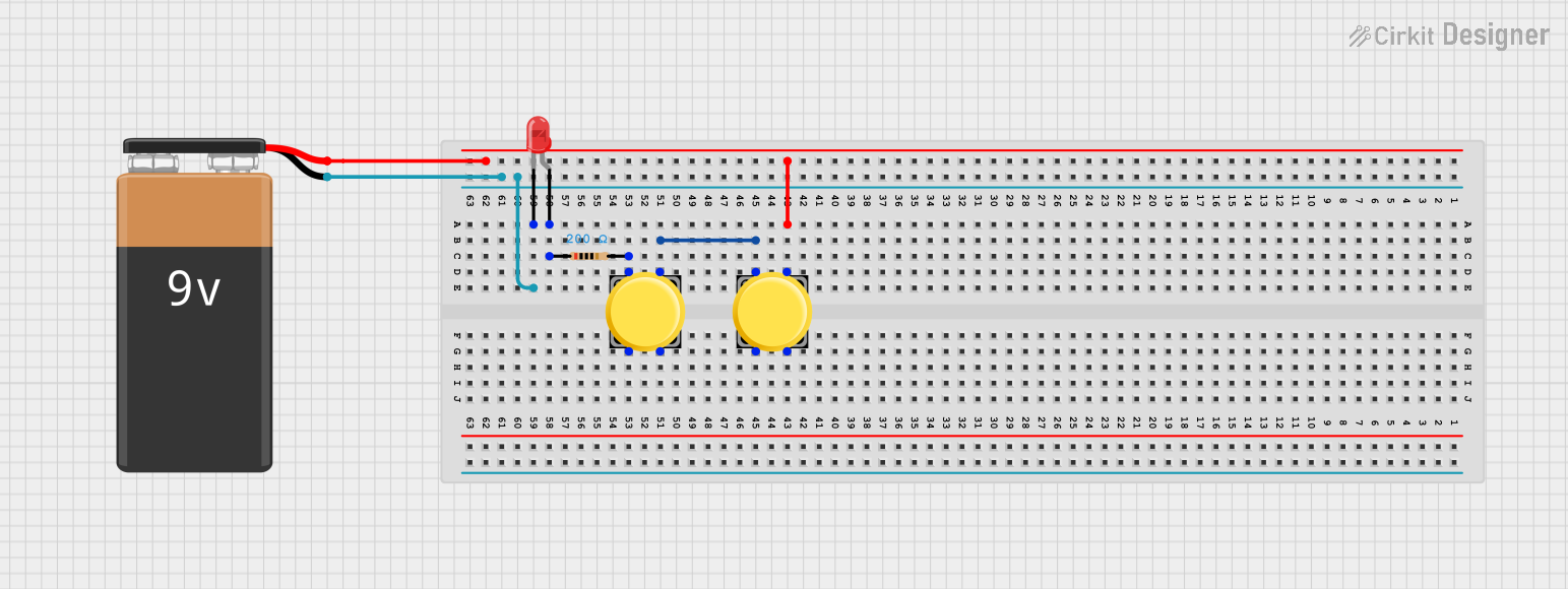
This circuit consists of a 9V battery, two pushbuttons, a red LED, and a resistor. The circuit is designed to control the LED using the pushbuttons. When the pushbuttons are pressed in sequence, the LED will light up.
Component List
9V Battery
- Description: Provides the power supply for the circuit.
- Pins: +, -
Pushbutton (1)
- Description: A pushbutton switch used to control the circuit.
- Pins: Pin 1, Pin 2, Pin 3, Pin 4
Pushbutton (2)
- Description: Another pushbutton switch used to control the circuit.
- Pins: Pin 1, Pin 2, Pin 3, Pin 4
LED: Two Pin (red)
- Description: A red LED that lights up when the circuit is completed.
- Pins: anode, cathode
Resistor
- Description: Limits the current flowing through the LED to prevent damage.
- Pins: pin1, pin2
- Properties:
- Resistance: 200 Ohms
Wiring Details
9V Battery
- + Pin:
- Connected to Pin 3 of Pushbutton (2)
- - Pin:
- Connected to the cathode of the LED
Pushbutton (1)
- Pin 1:
- Connected to Pin 3 of Pushbutton (2)
- Pin 2:
- Not connected
- Pin 3:
- Connected to Pin 1 of Pushbutton (2)
- Pin 4:
- Not connected
Pushbutton (2)
- Pin 1:
- Connected to pin2 of the Resistor
- Pin 2:
- Not connected
- Pin 3:
- Connected to the + pin of the 9V Battery
- Pin 4:
- Not connected
LED: Two Pin (red)
- anode:
- Connected to pin1 of the Resistor
- cathode:
- Connected to the - pin of the 9V Battery
Resistor
- pin1:
- Connected to the anode of the LED
- pin2:
- Connected to Pin 1 of Pushbutton (1)
Code
There is no microcontroller code associated with this circuit.