Arduino UNO Based Automated Plant Watering System with Environmental Monitoring
Circuit Documentation
Summary
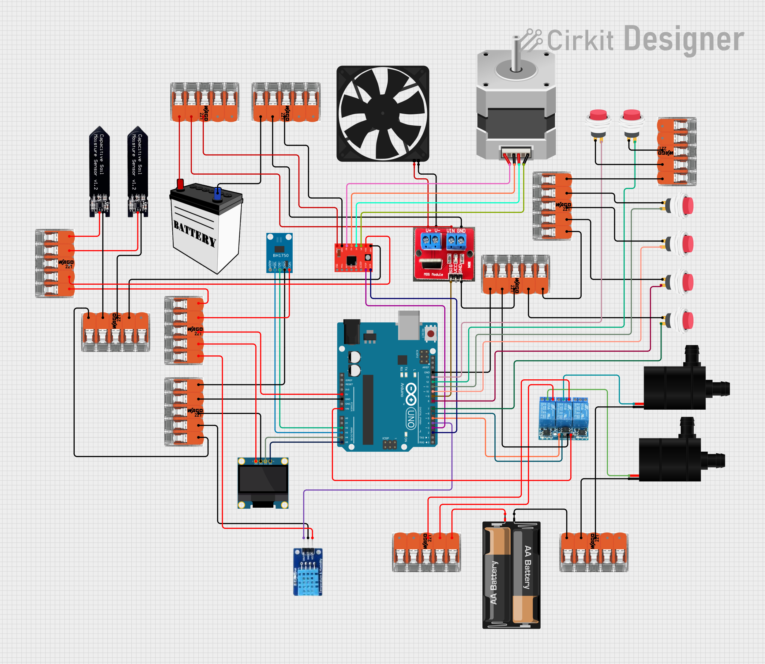
This circuit is designed around an Arduino UNO microcontroller, which serves as the central processing unit. The circuit includes various sensors, actuators, and interfaces, such as a BH1750 light sensor, an OLED display, a DHT11 temperature and humidity sensor, soil moisture sensors, a 3-channel relay module, water pumps, a fan, a stepper motor with its driver, and several push switches. Power is distributed through splicing connectors, and the circuit is powered by a combination of a 12V battery, a 2 x AA battery mount, and the Arduino's onboard voltage regulator.
Component List
- Arduino UNO: A microcontroller board based on the ATmega328P, featuring digital and analog I/O pins.
- BH1750: A digital light sensor that measures ambient light intensity.
- OLED 128x64 I2C Monochrome Display: A small display for outputting text and graphics.
- Splicing connector WAGO 221: A connector used for joining and managing multiple wire connections.
- Soil Moisture Sensor: A sensor used to measure the moisture content in soil.
- DHT11: A sensor that measures temperature and humidity.
- 3 Channel Relay 5V: A module with three relays to control high power devices.
- Water Pump: A pump for moving water, controlled by the relay module.
- IRF520 PWM Module: A MOSFET module for controlling devices like motors and LEDs with PWM.
- Fan: An electric fan for air circulation, controlled by the IRF520 module.
- 12V Battery: A battery providing the main power source for the circuit.
- 2 x AA Battery Mount: A battery holder for two AA batteries, providing additional power.
- Stepper Motor (Bipolar): A motor that moves in precise increments, used for positioning.
- A4988 Stepper Motor Driver: A driver module for controlling the stepper motor.
- 2Pin Push Switch: A simple push-button switch for user input.
Wiring Details
Arduino UNO
5Vconnected to 5V power distribution via a WAGO connector.GNDconnected to ground distribution via multiple WAGO connectors.Vinconnected to the VCC of the 3 Channel Relay 5V.A2andA3connected to SCL and SDA of the BH1750 light sensor, respectively.A4andA5connected to SCK and SDA of the OLED display, respectively.D2toD13connected to various components including the A4988 driver, IRF520 PWM module, push switches, and relay channels.
BH1750 Light Sensor
VCCandGNDconnected to power distribution via WAGO connectors.SCLandSDAconnected to Arduino UNO for I2C communication.
OLED Display
VDDandGNDconnected to power distribution via WAGO connectors.SCKandSDAconnected to Arduino UNO for I2C communication.
DHT11 Temperature and Humidity Sensor
DATAconnected toD4on the Arduino UNO.VCCandGNDconnected to power distribution via WAGO connectors.
Soil Moisture Sensors
- Both sensors have their
VCCandGNDconnected to power distribution via WAGO connectors.
3 Channel Relay 5V
VCCconnected toVinon the Arduino UNO.GNDconnected to ground distribution via a WAGO connector.CH1andCH2connected toD5andD6on the Arduino UNO, respectively.COMMONandNOconnected to the water pumps.
Water Pumps
VCCconnected to theCOMMONterminal of the relay module.GNDconnected to ground distribution via WAGO connectors.
IRF520 PWM Module
VinandGNDconnected to power distribution via WAGO connectors.SIGconnected toD9on the Arduino UNO.V+andV-connected to the fan.
Fan
5VandGNDconnected to the IRF520 PWM module.
A4988 Stepper Motor Driver
VMOTandGNDconnected to power distribution via WAGO connectors.VDDconnected to 5V power distribution via a WAGO connector.STEPandDIRconnected toD3andD2on the Arduino UNO, respectively.1A,1B,2A,2Bconnected to the stepper motor.
Stepper Motor (Bipolar)
A,B,C,Dconnected to the A4988 driver.
Push Switches
Input +connected to power distribution via WAGO connectors.Output +connected to various digital pins on the Arduino UNO.
Documented Code
void setup() {
  // put your setup code here, to run once:

}

void loop() {
  // put your main code here, to run repeatedly:

}
The provided code is a template with empty setup() and loop() functions, which are the entry points for Arduino sketches. The setup() function is called once when the sketch starts and is used for initializing settings, while the loop() function runs repeatedly, allowing the microcontroller to perform operations based on the circuit's design. Additional code would be required to control the components and read sensors in this circuit.