
Circuit Documentation
Summary
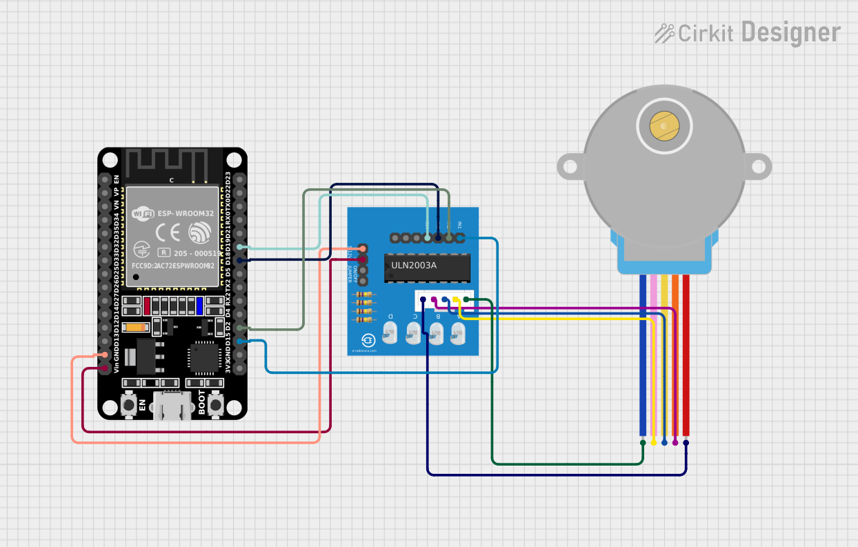
This document provides a detailed overview of a circuit that includes an ESP32 microcontroller, a ULN2003A breakout board, and a 28BYJ-48 stepper motor. The ESP32 controls the stepper motor through the ULN2003A driver. The document includes a list of components, wiring details, and any associated code.
Component List
ESP32 (30 pin)
- Description: A powerful microcontroller with built-in Wi-Fi and Bluetooth capabilities.
- Pins: EN, VP, VN, D34, D35, D32, D33, D25, D26, D27, D14, D12, D13, GND, Vin, D23, D22, TX0, RX0, D21, D19, D18, D5, TX2, RX2, D4, D2, D15, 3V3
28BYJ-48 Stepper Motor
- Description: A small, inexpensive stepper motor commonly used in various applications.
- Pins: BLUE, PINK, YELLOW, ORANGE, RED
ULN2003A Breakout Board
- Description: A driver board for controlling stepper motors, typically used with the 28BYJ-48 stepper motor.
- Pins: In 1, In 2, In 3, In 4, In 5, In 6, In 7, 0V, +5V, ON/OFF jumper switch, BLUE wire, PINK wire, YELLOW wire, ORANGE wire, RED wire
Wiring Details
ESP32 (30 pin)
- GND is connected to 0V on the ULN2003A breakout board.
- Vin is connected to +5V on the ULN2003A breakout board.
- D19 is connected to In 4 on the ULN2003A breakout board.
- D18 is connected to In 3 on the ULN2003A breakout board.
- D2 is connected to In 2 on the ULN2003A breakout board.
- D15 is connected to In 1 on the ULN2003A breakout board.
28BYJ-48 Stepper Motor
- BLUE is connected to BLUE wire on the ULN2003A breakout board.
- PINK is connected to PINK wire on the ULN2003A breakout board.
- YELLOW is connected to YELLOW wire on the ULN2003A breakout board.
- ORANGE is connected to ORANGE wire on the ULN2003A breakout board.
- RED is connected to RED wire on the ULN2003A breakout board.
ULN2003A Breakout Board
- 0V is connected to GND on the ESP32.
- +5V is connected to Vin on the ESP32.
- In 4 is connected to D19 on the ESP32.
- In 3 is connected to D18 on the ESP32.
- In 2 is connected to D2 on the ESP32.
- In 1 is connected to D15 on the ESP32.
- BLUE wire is connected to BLUE on the 28BYJ-48 stepper motor.
- PINK wire is connected to PINK on the 28BYJ-48 stepper motor.
- YELLOW wire is connected to YELLOW on the 28BYJ-48 stepper motor.
- ORANGE wire is connected to ORANGE on the 28BYJ-48 stepper motor.
- RED wire is connected to RED on the 28BYJ-48 stepper motor.
Code
No code is provided for this circuit.