
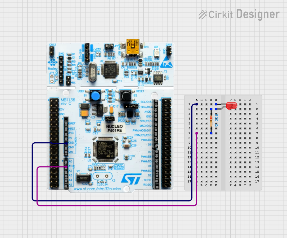
Circuit Documentation
Summary
This document provides a detailed description of a simple circuit involving an STM32 Nucleo-64 development board (Nucleo 401RE), a red LED, and a resistor. The circuit is designed to control the LED using the microcontroller, with the resistor limiting the current through the LED.
Component List
Nucleo 401RE
- Description: STM32 Nucleo-64 development board featuring the STM32F401RE microcontroller.
- Pins: IOREF, NRST, 3V3, 5V, GND, VIN, A0, A1, A2, A3, A4, A5, D0, D1, D2, D3, D4, D5, D6, D7, D8, D9, D10, D11, D12, D13, AVD0, D14, D15
LED: Two Pin (red)
- Description: A standard red LED with two pins: anode and cathode.
- Pins: cathode, anode
Resistor
- Description: A resistor with a resistance of 220 Ohms.
- Pins: pin1, pin2
- Properties:
- Resistance: 220 Ohms
Wiring Details
Nucleo 401RE
- GND is connected to the cathode of the LED.
- A1 is connected to pin2 of the resistor.
LED: Two Pin (red)
- cathode is connected to GND of the Nucleo 401RE.
- anode is connected to pin1 of the resistor.
Resistor
- pin1 is connected to the anode of the LED.
- pin2 is connected to A1 of the Nucleo 401RE.
Code Documentation
sketch.ino
void setup() {
  // put your setup code here, to run once:

}

void loop() {
  // put your main code here, to run repeatedly:

}
gpio.h
#ifndef __GPIO_H
#define __GPIO_H
#include "stdint.h"
void init_gpio(void);
void write_pin(int);
int read_pin(void);
#endif
test1.cpp
#include "gpio.h"
int main()
{
  init_gpio();
  while(1)
  {
    write_pin(read_pin());
    for(int i = 0; i<100; i++);
  }
}
gpio.cpp
#include "gpio.h"
#include "stm32f446xx.h"
void init_gpio(void)
{
  //enable PORT A for LED output
  RCC->AHB1ENR |= 1<<0;
  //Pin 1 output mode and speed for LED 1
  GPIOA->MODER |= 1<<2;
  GPIOA-> OSPEEDR |= 3<<2;

  //enable PORT C for button input
  RCC->AHB1ENR |= 1<<2;
  //Pin 13 input mode for the mounted button on PORT C Pin 13
  GPIOC->MODER &= ~(3<<26);
}

//reading the input from button, default = 1, pressed = 0
int read_pin(void){
  int value = 1;
  if (GPIOC->IDR & 1<<13){
    value = 0;
  }
  return value;
}

//turn led on based on button
void write_pin(int value)
{
  if (value == 1){
    //if pressed, LED 1 on
    GPIOA->BSRR |= 1<<1;
  }
  if (value == 0){
    //if not pressed, LED 1 off
    GPIOA->BSRR |= 1<<1<<16;
  }
}
This documentation provides a comprehensive overview of the circuit, including the components used, their connections, and the code running on the microcontroller.