
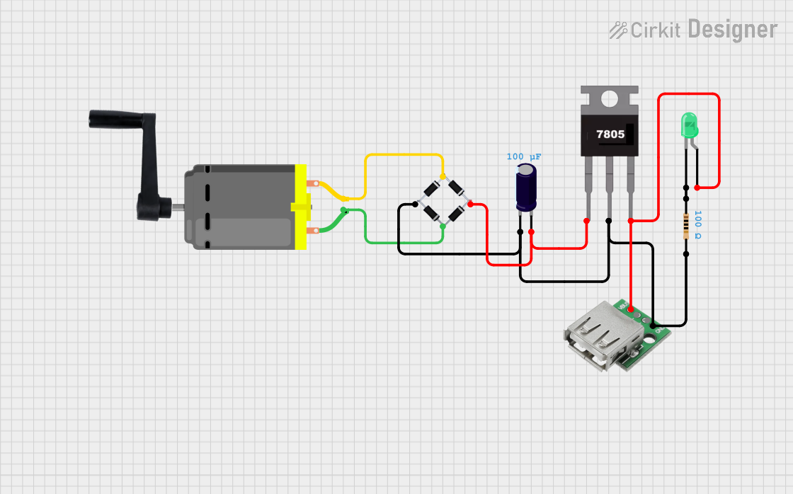
Circuit Documentation
Summary
This circuit is designed to convert mechanical energy into electrical energy using a hand-crank handle connected to a DC motor. The generated AC voltage is then rectified using a bridge rectifier and regulated to a stable 5V DC output using a 7805 voltage regulator. The circuit also includes an electrolytic capacitor for smoothing the output, a resistor and LED for indication, and a USB female connector for providing a 5V output.
Component List
DC Motor
- Description: Converts mechanical energy into electrical energy.
- Pins: pin 1, pin 2
Electrolytic Capacitor
- Description: Used for smoothing the rectified voltage.
- Pins: -, +
- Properties:
- Capacitance: 0.0001 Farads
7805 Voltage Regulator
- Description: Regulates the input voltage to a stable 5V DC output.
- Pins: Vin, Gnd, Vout
Hand-Crank Handle
- Description: Provides mechanical energy to the DC motor.
- Pins: None
Bridge Rectifier
- Description: Converts AC voltage to DC voltage.
- Pins: Source_in-, source_out-, source_out+, source_in+
USB Female Connector
- Description: Provides a 5V output for USB devices.
- Pins: VCC, GND, -D, +D
Resistor
- Description: Limits current to the LED.
- Pins: pin1, pin2
- Properties:
- Resistance: 100 Ohms
LED: Two Pin (green)
- Description: Provides visual indication of the circuit's operation.
- Pins: cathode, anode
Wiring Details
DC Motor
- pin 1 is connected to Bridge Rectifier source_in+
- pin 2 is connected to Bridge Rectifier Source_in-
Electrolytic Capacitor
- - is connected to:
- Bridge Rectifier source_out-
- 7805 Voltage Regulator Gnd
- Resistor pin2
- USB Female Connector GND
- + is connected to:
- Bridge Rectifier source_out+
- 7805 Voltage Regulator Vin
7805 Voltage Regulator
- Vin is connected to Bridge Rectifier source_out+
- Gnd is connected to:
- Bridge Rectifier source_out-
- Resistor pin2
- Electrolytic Capacitor -
- USB Female Connector GND
- Vout is connected to:
- LED: Two Pin (green) anode
- USB Female Connector VCC
Hand-Crank Handle
- No electrical connections
Bridge Rectifier
- source_in+ is connected to DC Motor pin 1
- Source_in- is connected to DC Motor pin 2
- source_out- is connected to:
- 7805 Voltage Regulator Gnd
- Resistor pin2
- Electrolytic Capacitor -
- USB Female Connector GND
- source_out+ is connected to:
- 7805 Voltage Regulator Vin
- Electrolytic Capacitor +
USB Female Connector
- VCC is connected to 7805 Voltage Regulator Vout
- GND is connected to:
- Bridge Rectifier source_out-
- 7805 Voltage Regulator Gnd
- Resistor pin2
- Electrolytic Capacitor -
Resistor
- pin1 is connected to LED: Two Pin (green) cathode
- pin2 is connected to:
- Bridge Rectifier source_out-
- 7805 Voltage Regulator Gnd
- Electrolytic Capacitor -
- USB Female Connector GND
LED: Two Pin (green)
- cathode is connected to Resistor pin1
- anode is connected to 7805 Voltage Regulator Vout
Code
No microcontroller code is present in this circuit.