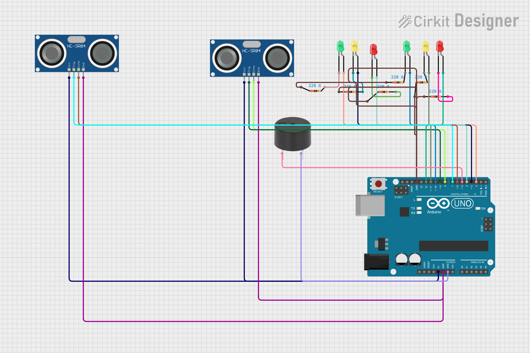
Arduino UNO Based Ultrasonic Distance Measurement with LED Indicators and Buzzer Alert

Circuit Documentation
Summary
This circuit is designed to utilize an Arduino UNO microcontroller to interface with two HC-SR04 Ultrasonic Sensors, a buzzer, and multiple LEDs of different colors (red, green, and yellow). The ultrasonic sensors are used to measure distances, and based on these measurements, the LEDs are controlled to indicate different distance ranges. Additionally, the buzzer is used to alert when an object is within a very close range to either of the sensors. The circuit is powered by the 5V output from the Arduino UNO, and ground connections are shared among the components.
Component List
Microcontroller
- Arduino UNO: A microcontroller board based on the ATmega328P. It has digital input/output pins, analog inputs, a USB connection for programming, and power management features.
Sensors
- HC-SR04 Ultrasonic Sensor: An ultrasonic distance sensor that provides 2cm to 400cm of non-contact measurement functionality with a ranging accuracy of up to 3mm.
Actuators
- Buzzer: An electromechanical component that emits sound when an electrical signal is applied.
Indicators
- LED: Two Pin (red): A red light-emitting diode used as an indicator.
- LED: Two Pin (green): A green light-emitting diode used as an indicator.
- LED: Two Pin (yellow): A yellow light-emitting diode used as an indicator.
Passive Components
- Resistor: A passive two-terminal electrical component that implements electrical resistance as a circuit element. In this circuit, 220 Ohm resistors are used to limit the current through the LEDs.
Wiring Details
Arduino UNO
- 5V pin connected to VCC pins of both HC-SR04 Ultrasonic Sensors.
- GND pin connected to GND pins of all components.
- Digital pins D2 to D12 are used to control LEDs and interface with the ultrasonic sensors and the buzzer.
HC-SR04 Ultrasonic Sensors
- VCC pin connected to 5V power supply from Arduino UNO.
- GND pin connected to common ground.
- TRIG and ECHO pins connected to specific digital pins on the Arduino UNO for triggering and receiving the ultrasonic pulses.
LEDs
- Anode pins connected to digital pins on the Arduino UNO through 220 Ohm resistors.
- Cathode pins connected to common ground.
Buzzer
- PIN connected to a digital pin on the Arduino UNO.
- GND connected to common ground.
Resistors
- One pin connected to the anode of an LED.
- The other pin connected to a digital pin on the Arduino UNO.
Documented Code
// Define pins for ultrasonic sensors
const int trigPin1 = 7;
const int echoPin1 = 6;
const int trigPin2 = 9;
const int echoPin2 = 8;

// Define LED pins (2 sets of 3 LEDs)
const int led1 = 2;
const int led2 = 3;
const int led3 = 4;
const int led4 = 10;
const int led5 = 11;
const int led6 = 12;

// Define Buzzer pin
const int buzzerPin = 5;

void setup() {
  // Initialize serial communication
  Serial.begin(9600);

  // Set pin modes for ultrasonic sensors
  pinMode(trigPin1, OUTPUT);
  pinMode(echoPin1, INPUT);
  pinMode(trigPin2, OUTPUT);
  pinMode(echoPin2, INPUT);

  // Set pin modes for LEDs
  pinMode(led1, OUTPUT);
  pinMode(led2, OUTPUT);
  pinMode(led3, OUTPUT);
  pinMode(led4, OUTPUT);
  pinMode(led5, OUTPUT);
  pinMode(led6, OUTPUT);

  // Set pin mode for buzzer
  pinMode(buzzerPin, OUTPUT);
}

long readUltrasonicDistance(int trigPin, int echoPin) {
  // Send a 10us pulse to trigger pin
  digitalWrite(trigPin, LOW);
  delayMicroseconds(2);
  digitalWrite(trigPin, HIGH);
  delayMicroseconds(10);
  digitalWrite(trigPin, LOW);

  // Read the pulse duration from echo pin
  long duration = pulseIn(echoPin, HIGH);

  // Convert to distance in cm
  long distance = duration * 0.034 / 2;
  return distance;
}

void controlLEDSet1(long distance) {
  // Control first set of LEDs based on decreasing distance
  if (distance < 10) {
    digitalWrite(led1, LOW);
    digitalWrite(led2, LOW);
    digitalWrite(led3, HIGH);  // Third LED on (closest distance)
  } else if (distance >= 10 && distance < 20) {
    digitalWrite(led1, LOW);
    digitalWrite(led2, HIGH);  // Second LED on
    digitalWrite(led3, LOW);
  } else if (distance >= 20) {
    digitalWrite(led1, HIGH);  // First LED on (farthest distance)
    digitalWrite(led2, LOW);
    digitalWrite(led3, LOW);
  }
}

void controlLEDSet2(long distance) {
  // Control second set of LEDs based on decreasing distance
  if (distance < 10) {
    digitalWrite(led4, LOW);
    digitalWrite(led5, LOW);
    digitalWrite(led6, HIGH);  // Third LED on (closest distance)
  } else if (distance >= 10 && distance < 20) {
    digitalWrite(led4, LOW);
    digitalWrite(led5, HIGH);  // Second LED on
    digitalWrite(led6, LOW);
  } else if (distance >= 20) {
    digitalWrite(led4, HIGH);  // First LED on (farthest distance)
    digitalWrite(led5, LOW);
    digitalWrite(led6, LOW);
  }
}

void controlBuzzerAndBlink(long distance1, long distance2) {
  // Blink third LEDs and activate buzzer when distance is less than 8 cm
  if (distance1 < 8 || distance2 < 8) {
    // Blink the last LEDs (led3 and led6)
    digitalWrite(led3, !digitalRead(led3));  // Toggle led3
    digitalWrite(led6, !digitalRead(led6));  // Toggle led6

    // Activate buzzer when either third LED is on
    if (digitalRead(led3) == HIGH || digitalRead(led6) == HIGH) {
      digitalWrite(buzzerPin, HIGH);  // Turn buzzer on
    } else {
      digitalWrite(buzzerPin, LOW);   // Turn buzzer off
    }
  } else {
    digitalWrite(buzzerPin, LOW);  // Buzzer off when out of range
  }
}

void loop() {
  // Read distances from both ultrasonic sensors
  long distance1 = readUltrasonicDistance(trigPin1, echoPin1);
  long distance2 = readUltrasonicDistance(trigPin2, echoPin2);

  // Control LEDs and buzzer
  controlLEDSet1(distance1);
  controlLEDSet2(distance2);
  controlBuzzerAndBlink(distance1, distance2);

  // Print distances to Serial Monitor (for debugging)
  Serial.print("Distance 1: ");
  Serial.print(distance1);
  Serial.print(" cm, Distance 2: ");
  Serial.println(distance2);

  delay(500);  // Short delay for blinking effect
}
This code is designed to be uploaded to the Arduino UNO microcontroller. It initializes the pins, defines the main loop, and includes functions to read distances from the ultrasonic sensors, control the LEDs, and operate the buzzer based on the sensor readings. The code also includes serial output for debugging purposes.