
Arduino UNO Solar Tracker with Light Sensors and Servo Motors
View and Edit Project In Cirkit Designer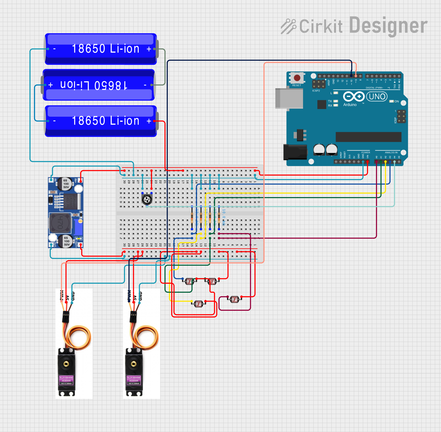
Circuit Documentation
Summary
This circuit is designed to control a dual-axis solar tracker using an Arduino UNO. The system uses four Light Dependent Resistors (LDRs) to detect the position of the sun and two servo motors to adjust the position of a solar panel. A trimmer potentiometer is used to control the speed of the servos. The circuit is powered by a 18650 Li-ion battery pack, regulated by a buck converter to provide a stable 5V supply.
Component List
Arduino UNO
- Description: Microcontroller board based on the ATmega328P.
- Pins: UNUSED, IOREF, Reset, 3.3V, 5V, GND, Vin, A0, A1, A2, A3, A4, A5, SCL, SDA, AREF, D13, D12, D11, D10, D9, D8, D7, D6, D5, D4, D3, D2, D1, D0
Buck Converter
- Description: DC-DC step-down converter.
- Pins: IN+, IN-, OUT+, OUT-
Servo Motor MG996R (2 units)
- Description: High-torque servo motor.
- Pins: PMW, VCC 5V, GND
Resistor (4 units)
- Description: Fixed resistor.
- Pins: pin1, pin2
- Properties: Resistance = 10,000 Ohms
Photocell (LDR) (4 units)
- Description: Light Dependent Resistor.
- Pins: pin 0, pin 1
Trimmer Potentiometer
- Description: Adjustable resistor.
- Pins: leg1, wiper, leg2
- Properties: Resistance = 10,000 Ohms
18650 Li-ion Battery (3 units)
- Description: Rechargeable lithium-ion battery.
- Pins: -, +
Wiring Details
Arduino UNO
- GND: Connected to the GND of the buck converter, trimmer potentiometer, and all resistors.
- Vin: Connected to the leg1 of the trimmer potentiometer and the positive terminal of one 18650 Li-ion battery.
- A0: Connected to pin2 of a resistor and pin1 of a photocell (LDR).
- A1: Connected to pin2 of a resistor and pin1 of a photocell (LDR).
- A2: Connected to pin2 of a resistor and pin1 of a photocell (LDR).
- A3: Connected to pin2 of a resistor and pin1 of a photocell (LDR).
- A4: Connected to the wiper of the trimmer potentiometer.
- D9: Connected to the PMW pin of one servo motor.
- D10: Connected to the PMW pin of the other servo motor.
Buck Converter
- IN+: Connected to the positive terminal of one 18650 Li-ion battery and leg1 of the trimmer potentiometer.
- IN-: Connected to the GND of the Arduino UNO, trimmer potentiometer, and all resistors.
- OUT+: Connected to the VCC 5V pins of both servo motors and pin0 of all photocells (LDRs).
- OUT-: Connected to the GND pins of both servo motors.
Servo Motor MG996R
- PMW: Connected to D9 (one servo) and D10 (other servo) of the Arduino UNO.
- VCC 5V: Connected to OUT+ of the buck converter.
- GND: Connected to OUT- of the buck converter.
Resistor
- pin1: Connected to the GND of the Arduino UNO, trimmer potentiometer, and buck converter.
- pin2: Connected to A0, A1, A2, and A3 of the Arduino UNO and pin1 of each corresponding photocell (LDR).
Photocell (LDR)
- pin 0: Connected to OUT+ of the buck converter.
- pin 1: Connected to pin2 of each corresponding resistor and A0, A1, A2, and A3 of the Arduino UNO.
Trimmer Potentiometer
- leg1: Connected to Vin of the Arduino UNO and the positive terminal of one 18650 Li-ion battery.
- wiper: Connected to A4 of the Arduino UNO.
- leg2: Connected to the GND of the Arduino UNO, buck converter, and all resistors.
18650 Li-ion Battery
- -: Connected to the GND of the Arduino UNO, buck converter, and all resistors.
- +: Connected to Vin of the Arduino UNO and leg1 of the trimmer potentiometer.
Code Documentation
#include <Servo.h>

// Define servos for horizontal and vertical axes
Servo servoHor; // Horizontal Servo
Servo servoVer; // Vertical Servo

// Define LDR pins for light detection (connected to analog pins)
const int ldrTL = A0; // Top-Left LDR
const int ldrTR = A1; // Top-Right LDR
const int ldrBL = A2; // Bottom-Left LDR
const int ldrBR = A3; // Bottom-Right LDR

// Potentiometer pin for speed control
const int potPin = A4;

// Variables to hold LDR values
int valTL, valTR, valBL, valBR;

// Servo speed control
int servoSpeed;

// Initialize positions for servos
int posHor = 90; // Start horizontal servo at the center (90 degrees)
int posVer = 90; // Start vertical servo at the center (90 degrees)

void setup() {
  // Attach servos to digital pins
  servoHor.attach(9);  // Horizontal servo on pin 9
  servoVer.attach(10); // Vertical servo on pin 10

  // Set initial positions
  servoHor.write(posHor);
  servoVer.write(posVer);

  // Initialize serial monitor (optional, for debugging)
  Serial.begin(9600);
}

void loop() {
  // Read LDR sensor values
  valTL = analogRead(ldrTL);
  valTR = analogRead(ldrTR);
  valBL = analogRead(ldrBL);
  valBR = analogRead(ldrBR);

  // Read potentiometer value and map it to a range for servo speed (0 to 10)
  servoSpeed = map(analogRead(potPin), 0, 1023, 0, 10);

  // Horizontal movement: compare light levels between top-left and top-right LDRs
  if (abs(valTL - valTR) > 10) { // Sensitivity threshold to prevent jitter
    if (valTL < valTR) {
      posHor -= servoSpeed; // Move left
    } else {
      posHor += servoSpeed; // Move right
    }
  }

  // Vertical movement: compare light levels between bottom-left and bottom-right LDRs
  if (abs(valBL - valBR) > 10) { // Sensitivity threshold
    if (valBL < valBR) {
      posVer -= servoSpeed; // Move down
    } else {
      posVer += servoSpeed; // Move up
    }
  }

  // Constrain the servo positions to ensure they stay within range (0-180 degrees)
  posHor = constrain(posHor, 0, 180);
  posVer = constrain(posVer, 0, 180);

  // Move the servos to the new positions
  servoHor.write(posHor);
  servoVer.write(posVer);

  // Debugging: print out values to the serial monitor
  Serial.print("TL: "); Serial.print(valTL);
  Serial.print(" TR: "); Serial.print(valTR);
  Serial.print(" BL: "); Serial.print(valBL);
  Serial.print(" BR: "); Serial.println(valBR);

  // Small delay to allow servo to move
  delay(50);
}
This code initializes and controls two servo motors based on the input from four LDR sensors and a potentiometer. The servos adjust the position of the solar panel to track the sun, ensuring optimal light exposure.