
Circuit Documentation
Summary
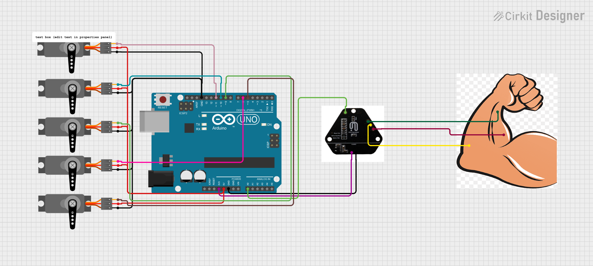
This circuit is designed to interface an ECG sensor with an Arduino UNO to control multiple servos. The ECG sensor reads the electrical activity of the heart, and the Arduino processes this data to control the movement of the servos, which can be used to simulate finger movements.
Component List
EXG Sensor
- Description: Measures electrical activity of the heart.
- Pins: -IN, DRL, +IN, OUT, GND, +3.3V
Arduino UNO
- Description: Microcontroller board based on the ATmega328P.
- Pins: UNUSED, IOREF, Reset, 3.3V, 5V, GND, Vin, A0, A1, A2, A3, A4, A5, SCL, SDA, AREF, D13, D12, D11, D10, D9, D8, D7, D6, D5, D4, D3, D2, D1, D0
Hand
- Description: Simulated hand with input pins.
- Pins: DNL, +IN, -IN
Servo (x5)
- Description: Actuators for controlling finger movements.
- Pins: GND, VCC, PWM
Wiring Details
EXG Sensor
- -IN: Connected to Hand -IN
- DRL: Connected to Hand DNL
- +IN: Connected to Hand +IN
- OUT: Connected to Arduino UNO A0
- GND: Connected to Arduino UNO GND
- +3.3V: Connected to Arduino UNO 3.3V
Arduino UNO
- A0: Connected to EXG Sensor OUT
- GND: Connected to EXG Sensor GND and all Servo GND pins
- 3.3V: Connected to EXG Sensor +3.3V
- 5V: Connected to all Servo VCC pins
- D5: Connected to Servo PWM pin
- D6: Connected to Servo PWM pin
- D9: Connected to Servo PWM pin
- D10: Connected to Servo PWM pin
- D11: Connected to Servo PWM pin
Hand
- -IN: Connected to EXG Sensor -IN
- DNL: Connected to EXG Sensor DRL
- +IN: Connected to EXG Sensor +IN
Servo (x5)
- GND: Connected to Arduino UNO GND
- VCC: Connected to Arduino UNO 5V
- PWM:
- Servo 1: Connected to Arduino UNO D5
- Servo 2: Connected to Arduino UNO D6
- Servo 3: Connected to Arduino UNO D9
- Servo 4: Connected to Arduino UNO D10
- Servo 5: Connected to Arduino UNO D11
Code Documentation
#include <Servo.h>

#define ECG_PIN A0   // Analog pin for AD8232 output
#define SERVO_PIN_1 9  // Pin for Servo 1 (e.g., thumb)
#define SERVO_PIN_2 10 // Pin for Servo 2 (e.g., index)
#define SERVO_PIN_3 11 // Pin for Servo 3 (e.g., middle)
#define SERVO_PIN_4 12 // Pin for Servo 4 (e.g., ring)
#define SERVO_PIN_5 13 // Pin for Servo 5 (e.g., pinky)

Servo servo1, servo2, servo3, servo4, servo5;

int sensorValue = 0;  // Variable to store ECG sensor data
int mappedValue = 0;  // Mapped value for servo movement

void setup() {
  // Attach the servos to the respective pins
  servo1.attach(SERVO_PIN_1);
  servo2.attach(SERVO_PIN_2);
  servo3.attach(SERVO_PIN_3);
  servo4.attach(SERVO_PIN_4);
  servo5.attach(SERVO_PIN_5);

  // Initialize the servos at a neutral position (0°)
  servo1.write(90);
  servo2.write(90);
  servo3.write(90);
  // servo4.write(90);
  servo5.write(90);

  // Start serial communication for debugging
  Serial.begin(9600);
}

void loop() {
  // Read the value from the AD8232 ECG sensor
  sensorValue = analogRead(ECG_PIN);

  // Map the sensor value to a suitable range for servo movement (e.g., 0-180 degrees)
  mappedValue = map(sensorValue, 0, 1023, 0, 180);

  // Move each servo based on the sensor data (you can adjust logic as needed)
  servo1.write(mappedValue);  // Move the first finger
  servo2.write(mappedValue);  // Move the second finger
  servo3.write(mappedValue);  // Move the third finger
  servo4.write(mappedValue);  // Move the fourth finger
  servo5.write(mappedValue);  // Move the fifth finger

  // Print the sensor value and mapped servo position for debugging
  Serial.print("Sensor Value: ");
  Serial.print(sensorValue);
  Serial.print(" Mapped Value: ");
  Serial.println(mappedValue);

  // Add a small delay to allow the servos to move
  delay(100);
}
This code initializes the servos and reads the ECG sensor data. The sensor data is then mapped to a range suitable for servo movement, and the servos are moved accordingly. The sensor value and mapped value are printed to the serial monitor for debugging purposes.