
Arduino UNO-Based Environmental Monitoring System with Motion-Activated Relays
View and Edit Project In Cirkit Designer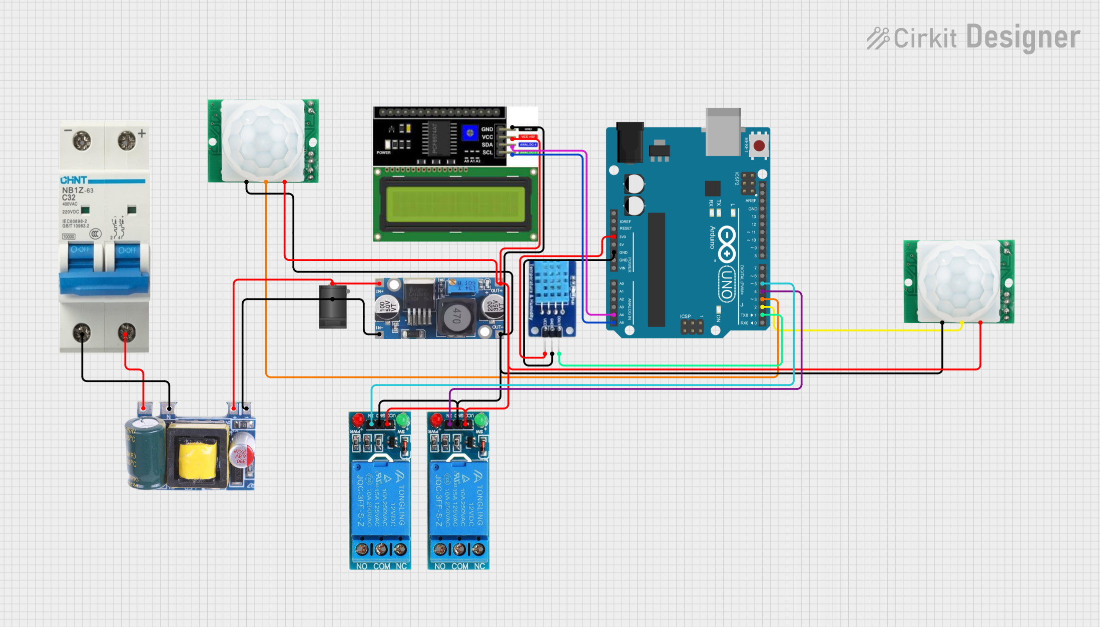
Circuit Documentation
Summary
This circuit integrates various components controlled by an Arduino UNO microcontroller to perform a series of tasks. The Arduino UNO interfaces with an LCD I2C display for user interaction, a DHT11 sensor for temperature and humidity readings, two HC-SR501 motion sensors for detecting movement, and two 12V single-channel relays for controlling external devices. A step-down buck converter is used to regulate voltage for the relays and sensors, and a mini AC-DC converter module provides a 5V supply from an AC source, with a circuit breaker for protection. The circuit is designed to be powered through a 2.1mm DC barrel jack.
Component List
- Arduino UNO: A microcontroller board based on the ATmega328P, featuring digital and analog I/O pins.
- LCD I2C Display: A liquid crystal display with an I2C interface for showing data and messages.
- Step-down Buck Converter: A voltage regulator that steps down input voltage to a lower output voltage.
- 2.1mm DC Barrel Jack: A power connector for supplying power to the circuit.
- DHT11: A basic, ultra-low-cost digital temperature and humidity sensor.
- HC-SR501 Motion Sensor: A PIR motion sensor for detecting movement within its detection range.
- 12V Single Channel Relay: An electromechanical switch that allows control of a high power circuit by a low power signal.
- Mini AC-DC 110V-230V to 5V 700mA Module: A power supply module that converts AC voltage to a 5V DC output.
- Circuit Breaker: A safety device that breaks the circuit when excessive current flows through it.
Wiring Details
Arduino UNO
- 3.3V to DHT11 VCC
- GND to DHT11 GND, LCD I2C Display GND, both HC-SR501 Motion Sensors GND, and both 12V Single Channel Relays GND
- A4 (SDA) to LCD I2C Display SDA
- A5 (SCL) to LCD I2C Display SCL
- D5 to 12V Single Channel Relay IN (1st relay)
- D4 to 12V Single Channel Relay IN (2nd relay)
- D3 to HC-SR501 Motion Sensor OUT (1st sensor)
- D2 to HC-SR501 Motion Sensor OUT (2nd sensor)
- D1 to DHT11 DATA
LCD I2C Display
- VCC to 5V supply net
- GND to GND net
- SDA to Arduino UNO A4
- SCL to Arduino UNO A5
Step-down Buck Converter
- IN + to 5V supply net
- IN - GND to GND net
- OUT + to 12V supply net
- OUT - GND to GND net
2.1mm DC Barrel Jack
- Center to 5V supply net
- Switch to GND net
DHT11
- VCC to Arduino UNO 3.3V
- GND to GND net
- DATA to Arduino UNO D1
HC-SR501 Motion Sensor
- VCC to 5V supply net
- GND to GND net
- OUT to Arduino UNO D3 (1st sensor) and D2 (2nd sensor)
12V Single Channel Relay
- VCC to 12V supply net
- GND to GND net
- IN to Arduino UNO D5 (1st relay) and D4 (2nd relay)
Mini AC-DC 110V-230V to 5V 700mA Module
- 5V to 5V supply net
- GND to GND net
- Neutral to Circuit Breaker -
- Life to Circuit Breaker +
Circuit Breaker
- - to Mini AC-DC Module Neutral
- + to Mini AC-DC Module Life
Documented Code
Arduino UNO Sketch (sketch.ino)
void setup() {
  // put your setup code here, to run once:

}

void loop() {
  // put your main code here, to run repeatedly:

}
Additional Notes (documentation.txt)
The provided code is a template and does not contain any functional code. It is expected that the user will add the necessary setup and loop code to interact with the connected components as per the requirements of the application.