
Arduino UNO R4 WiFi-Based Multi-Sensor Monitoring System with LCD Display
View and Edit Project In Cirkit Designer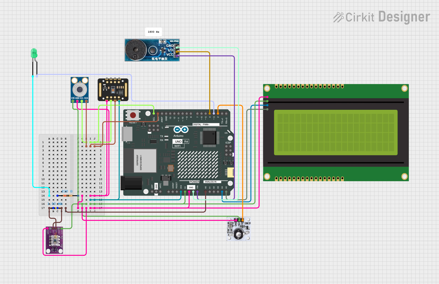
Circuit Documentation
Summary
This document provides a detailed overview of a circuit that includes an Arduino UNO R4 WiFi microcontroller, various sensors, an LCD panel, an LED, a buzzer, and resistors. The circuit is designed to interface multiple sensors and output devices with the Arduino, allowing for data collection and display.
Component List
Arduino UNO R4 WiFi
- Description: A microcontroller board based on the ATmega328P, featuring built-in WiFi capabilities.
- Pins: OFF, GND, VRTC, IIC0_SCL, IIC0_SDA, 3V3, GPIO 41, GPIO 0, GPIO 42, GPIO 43, GPIO 44, BOOT, IOREF, RESET, 5V, VIN, A0, A1, A2, A3, A4, A5, RSPCKA, CIPO, COPI, D0/RX, D1/TX, D2, D3, D4, D5, D6, D7, D8, D9, D10, D11, D12, D13, AREF, SDA, SCL
20x4 I2C LCD Panel
- Description: A 20x4 character LCD display with I2C interface.
- Pins: GND, VCC, SDA, SCL
OPT101 Light Sensor
- Description: A monolithic photodiode and single-supply transimpedance amplifier.
- Pins: VCC, GND, OUT, -V, COM, 1M
mlx90614
- Description: An infrared thermometer for non-contact temperature measurements.
- Pins: SDA, SCL, GND, VIN
940nm Infrared LED Transmitter Module
- Description: An infrared LED module for transmitting IR signals.
- Pins: IN, 5V, GND
MAX30102
- Description: A pulse oximeter and heart-rate sensor module.
- Pins: VIN, SDA, SCL, GND, RD, IRD, INT
LED: Two Pin (green)
- Description: A standard green LED with two pins.
- Pins: cathode, anode
Resistor (1M Ohm)
- Description: A resistor with a resistance of 1M Ohm.
- Pins: pin1, pin2
Resistor (220 Ohm)
- Description: A resistor with a resistance of 220 Ohm.
- Pins: pin1, pin2
Buzzer Module
- Description: A module that produces sound when powered.
- Pins: GND, Vcc, I/O
Wiring Details
Arduino UNO R4 WiFi
- GND: Connected to GND of MAX30102, mlx90614, 20x4 I2C LCD Panel, OPT101 Light Sensor, 940nm Infrared LED Transmitter Module, and Buzzer Module.
- 3V3: Connected to VIN of MAX30102.
- 5V: Connected to VCC of 20x4 I2C LCD Panel, VCC of OPT101 Light Sensor, 5V of 940nm Infrared LED Transmitter Module, and VIN of mlx90614.
- A0: Connected to OUT and 1M of OPT101 Light Sensor.
- A4: Connected to SDA of 20x4 I2C LCD Panel.
- A5: Connected to SCL of 20x4 I2C LCD Panel.
- D2: Connected to IN of 940nm Infrared LED Transmitter Module.
- D3: Connected to anode of LED: Two Pin (green).
- D4: Connected to I/O of Buzzer Module.
- SDA: Connected to SDA of MAX30102 and mlx90614.
- SCL: Connected to SCL of MAX30102 and mlx90614.
20x4 I2C LCD Panel
- GND: Connected to GND of Arduino UNO R4 WiFi.
- VCC: Connected to 5V of Arduino UNO R4 WiFi.
- SDA: Connected to A4 of Arduino UNO R4 WiFi.
- SCL: Connected to A5 of Arduino UNO R4 WiFi.
OPT101 Light Sensor
- VCC: Connected to 5V of Arduino UNO R4 WiFi.
- GND: Connected to GND of Arduino UNO R4 WiFi.
- OUT: Connected to A0 of Arduino UNO R4 WiFi.
- COM: Connected to GND of Arduino UNO R4 WiFi.
- 1M: Connected to A0 of Arduino UNO R4 WiFi.
mlx90614
- SDA: Connected to SDA of Arduino UNO R4 WiFi.
- SCL: Connected to SCL of Arduino UNO R4 WiFi.
- GND: Connected to GND of Arduino UNO R4 WiFi.
- VIN: Connected to 5V of Arduino UNO R4 WiFi.
940nm Infrared LED Transmitter Module
- IN: Connected to D2 of Arduino UNO R4 WiFi.
- 5V: Connected to 5V of Arduino UNO R4 WiFi.
- GND: Connected to GND of Arduino UNO R4 WiFi.
MAX30102
- VIN: Connected to 3V3 of Arduino UNO R4 WiFi.
- SDA: Connected to SDA of Arduino UNO R4 WiFi.
- SCL: Connected to SCL of Arduino UNO R4 WiFi.
- GND: Connected to GND of Arduino UNO R4 WiFi.
LED: Two Pin (green)
- cathode: Connected to pin1 of 220 Ohm Resistor.
- anode: Connected to D3 of Arduino UNO R4 WiFi.
Resistor (1M Ohm)
- pin1: Connected to pin2 of 1M Ohm Resistor.
- pin2: Connected to OUT and 1M of OPT101 Light Sensor.
Resistor (220 Ohm)
- pin1: Connected to cathode of LED: Two Pin (green).
- pin2: Connected to GND of Arduino UNO R4 WiFi.
Buzzer Module
- GND: Connected to GND of Arduino UNO R4 WiFi.
- Vcc: Connected to VIN of Arduino UNO R4 WiFi.
- I/O: Connected to D4 of Arduino UNO R4 WiFi.
Documented Code
Arduino UNO R4 WiFi Code
void setup() {
  // put your setup code here, to run once:

}

void loop() {
  // put your main code here, to run repeatedly:

}
This code is a basic template for the Arduino UNO R4 WiFi. The setup function is used to initialize any settings or configurations, and the loop function contains the main code that runs repeatedly.