
ESP32-Based Smart Notification System with LED Indicators and Buzzer
View and Edit Project In Cirkit Designer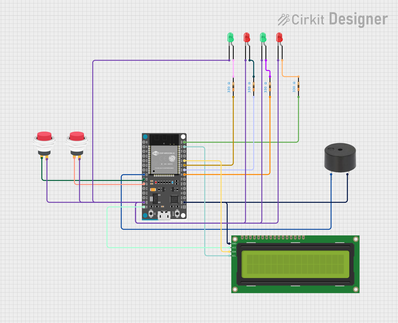
Circuit Documentation
Summary
This circuit is designed to provide a notification system indicating the presence of individuals in a specific area. It utilizes an ESP32 microcontroller to control LEDs, a buzzer, and an LCD display. The system is integrated with the Blynk platform for remote monitoring and notifications.
Component List
Buzzer
- Pins: PIN, GND
- Description: Emits sound for notifications.
- Purpose: Used to alert users with an audible signal.
LED: Two Pin (red)
- Pins: Cathode, Anode
- Description: Red LED for visual indication.
- Purpose: Indicates the status of individuals.
LED: Two Pin (green)
- Pins: Cathode, Anode
- Description: Green LED for visual indication.
- Purpose: Indicates the status of individuals.
ESP32 Devkit V1
- Pins: 3V3, GND, D15, D2, D4, RX2, TX2, D5, D18, D19, D21, RX0, TX0, D22, D23, EN, VP, VN, D34, D35, D32, D33, D25, D26, D27, D14, D12, D13, VIN
- Description: Microcontroller for controlling the circuit.
- Purpose: Central control unit for the circuit.
2Pin Push Switch
- Pins: Input +, Output +
- Description: Push button switch.
- Purpose: Used to trigger events in the circuit.
16x2 I2C LCD
- Pins: GND, VCC, SDA, SCL
- Description: LCD display for showing messages.
- Purpose: Displays status messages.
Resistor (330 Ohms)
- Pins: Pin1, Pin2
- Description: Resistor with 330 Ohms resistance.
- Purpose: Current limiting for LEDs.
Wiring Details
Buzzer
- PIN connected to ESP32 Devkit V1 pin D25
- GND connected to ESP32 Devkit V1 pin GND
LED: Two Pin (red)
- Anode connected to Resistor pin Pin2
- Cathode connected to ESP32 Devkit V1 pin GND
LED: Two Pin (green)
- Anode connected to Resistor pin Pin2
- Cathode connected to ESP32 Devkit V1 pin GND
ESP32 Devkit V1
- D25 connected to Buzzer pin PIN
- GND connected to Buzzer pin GND
- D5 connected to Resistor pin Pin1
- D18 connected to Resistor pin Pin1
- D19 connected to Resistor pin Pin1
- D21 connected to 16x2 I2C LCD pin SDA
- D22 connected to 16x2 I2C LCD pin SCL
- D23 connected to Resistor pin Pin1
- D26 connected to 2Pin Push Switch pin Input +
- D27 connected to 2Pin Push Switch pin Input +
- VIN connected to 16x2 I2C LCD pin VCC
2Pin Push Switch
- Input + connected to ESP32 Devkit V1 pin D26
- Output + connected to LED: Two Pin (red) pin Cathode
16x2 I2C LCD
- GND connected to ESP32 Devkit V1 pin GND
- VCC connected to ESP32 Devkit V1 pin VIN
- SDA connected to ESP32 Devkit V1 pin D21
- SCL connected to ESP32 Devkit V1 pin D22
Resistor (330 Ohms)
- Pin1 connected to ESP32 Devkit V1 pin D5
- Pin2 connected to LED: Two Pin (red) pin Anode
Resistor (330 Ohms)
- Pin1 connected to ESP32 Devkit V1 pin D18
- Pin2 connected to LED: Two Pin (green) pin Anode
Resistor (330 Ohms)
- Pin1 connected to ESP32 Devkit V1 pin D19
- Pin2 connected to LED: Two Pin (red) pin Anode
Resistor (330 Ohms)
- Pin1 connected to ESP32 Devkit V1 pin D23
- Pin2 connected to LED: Two Pin (green) pin Anode
Documented Code
#define BLYNK_TEMPLATE_ID "TMPL68lOFeQQw"
#define BLYNK_TEMPLATE_NAME "SISTEM NOTIFIKASI KEBERADAAN PENGAJAR DI JABATAN"
#define BLYNK_AUTH_TOKEN "8DoDKWs8kXsOqmrErjOt_xIueKSFkMV0"

#define BLYNK_PRINT Serial
#include <WiFi.h>
#include <WiFiClient.h>
#include <BlynkSimpleEsp32.h>
#include <Wire.h>
#include <LiquidCrystal_I2C.h>
LiquidCrystal_I2C lcd(0x27, 16,2);
#define ledred1   23
#define ledgreen1 19
#define ledred2   18
#define ledgreen2 5
#define buzzer 25

char auth[] = BLYNK_AUTH_TOKEN;
char ssid[] = "Zul";
char pass[] = "zul54321";
int pinData;
int param;

BLYNK_WRITE(V0)
{
  int pinValue = param.asInt();
  if(pinValue == 0){
    lcd.setCursor(0,0);
    lcd.print("AZMAN   - TIADA ");
    digitalWrite(ledred1,HIGH);
    digitalWrite(ledgreen1,LOW);
  }
  else if(pinValue == 1){
    lcd.setCursor(0,0);
    lcd.print("AZMAN   - ADA  ");
    digitalWrite(ledred1,LOW);
    digitalWrite(ledgreen1,HIGH);
  }
  else if(pinValue == 2){
    digitalWrite(buzzer,HIGH);
    lcd.setCursor(0,0);
    lcd.print("AZMAN  - MASUK   ");
    delay(3000);
    digitalWrite(buzzer,LOW);
  }
  else if(pinValue == 3){
    digitalWrite(buzzer,HIGH);
    lcd.setCursor(0,0);
    lcd.print("AZMAN  - SIBUK  ");
    delay(3000);
    digitalWrite(buzzer,LOW);
  }
}
BLYNK_WRITE(V1)
{
  int pinValue = param.asInt();
  if(pinValue == 0){
    lcd.setCursor(0,1);
    lcd.print("SHAKIRAH - TIADA  ");
    digitalWrite(ledred2,HIGH);
    digitalWrite(ledgreen2,LOW);
  }
  else if(pinValue == 1){
    lcd.setCursor(0,1);
    lcd.print("SHAKIRAH - ADA  ");
    digitalWrite(ledred2,LOW);
    digitalWrite(ledgreen2,HIGH);
  }
  else if(pinValue == 2){
    digitalWrite(buzzer,HIGH);
    lcd.setCursor(0,1);
    lcd.print("SHAKIRAH - MASUK   ");
    delay(3000);
    digitalWrite(buzzer,LOW);
  }
  else if(pinValue == 3){
    digitalWrite(buzzer,HIGH);
    lcd.setCursor(0,1);
    lcd.print("SHAKIRAH - SIBUK  ");
    delay(3000);
    digitalWrite(buzzer,LOW);
  }
}
void setup()
{
    Serial.begin(9600);
    Blynk.begin(auth, ssid, pass);
    pinMode(26,INPUT_PULLUP);
    pinMode(27,INPUT_PULLUP);
    pinMode(ledred1,OUTPUT);
    pinMode(ledgreen1,OUTPUT);
    pinMode(ledred2,OUTPUT);
    pinMode(ledgreen2,OUTPUT);
    pinMode(buzzer,OUTPUT);
    lcd.begin();
    lcd.backlight();
    lcd.setCursor(0,0);
    lcd.print("AZMAN   - TIADA");
    lcd.setCursor(0,1);
    lcd.print("SHAKIRAH - TIADA");
    digitalWrite(buzzer,LOW);
    digitalWrite(ledred1,HIGH);
    digitalWrite(ledgreen1,LOW);
    digitalWrite(ledred2,HIGH);
    digitalWrite(ledgreen2,LOW);
}

void loop()
{
   Blynk.run();
   Blynk.syncVirtual(V0);