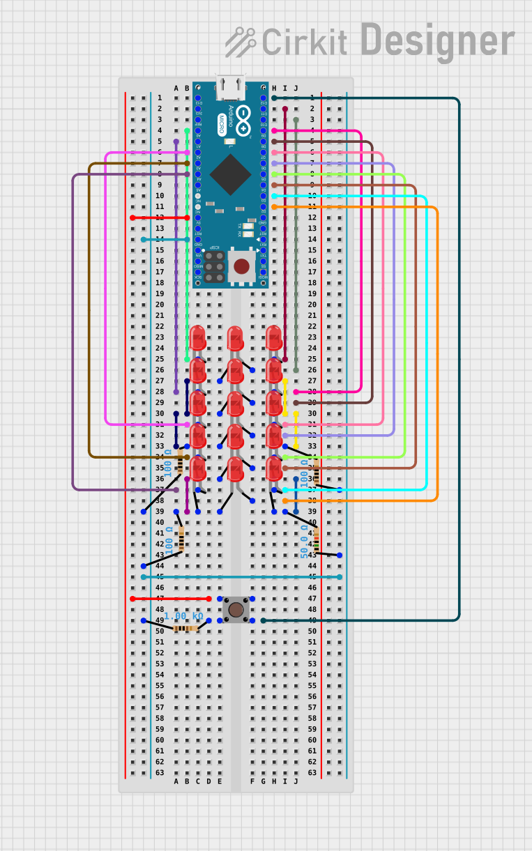
Arduino Micro-Controlled LED Array with Pushbutton Interaction

Circuit Documentation
Summary
This circuit is designed around an Arduino Micro (Rev3) microcontroller and includes multiple red LEDs, resistors, and a pushbutton. The LEDs are controlled by various digital and analog pins on the Arduino, and current-limiting resistors are used to protect the LEDs. The pushbutton is connected to one of the digital pins and is used to trigger an input. The circuit appears to be set up for a simple LED control application, with the potential for user interaction via the pushbutton.
Component List
Microcontroller
- Arduino Micro (Rev3): A microcontroller board based on the ATmega32U4. It has 20 digital input/output pins (of which 7 can be used as PWM outputs and 12 as analog inputs), a 16 MHz crystal oscillator, a micro USB connection, an ICSP header, and a reset button.
LEDs
- LED: Two Pin (red): A basic red LED with an anode and cathode for emitting red light when powered.
Resistors
- Resistor (100 Ohms): A resistor with a resistance of 100 Ohms, typically used for current limiting in LED circuits.
- Resistor (50 Ohms): A resistor with a resistance of 50 Ohms, used for current limiting or other purposes in the circuit.
- Resistor (1000 Ohms): A resistor with a resistance of 1000 Ohms, also known as a 1k Ohm resistor, used for current limiting or voltage dropping.
Pushbutton
- Pushbutton: A simple pushbutton switch that can connect or disconnect circuits when pressed.
Wiring Details
Arduino Micro (Rev3)
- Digital pins (D2 to D13) and analog pins (A0 to A5) are used to control LEDs.
- Pin D12 is connected to the pushbutton.
- 5V and GND pins provide power to the pushbutton and the resistors connected to the LED cathodes.
LEDs
- Each LED has its anode connected to a specific pin on the Arduino for individual control.
- The cathodes of the LEDs are connected to ground through current-limiting resistors.
Resistors
- 100 Ohm Resistors: Connected in series with the LEDs to limit the current through them.
- 50 Ohm Resistor: Connected in series with an LED or another part of the circuit for current limiting.
- 1000 Ohm Resistor: Connected to the pushbutton to form a pull-down or pull-up resistor network.
Pushbutton
- One side is connected to the 5V supply through the Arduino.
- The other side is connected to the Arduino's digital pin D12 and to ground through a 1000 Ohm resistor.
Documented Code
Arduino Micro (Rev3) - sketch.ino
void setup() {
  // put your setup code here, to run once:

}

void loop() {
  // put your main code here, to run repeatedly:

}
This code is a template and does not contain any functional code. It provides the basic structure for an Arduino sketch with setup() and loop() functions. The setup() function is intended for code that runs once at the start, such as pin initialization. The loop() function is for code that runs continuously.
Additional Notes
- The provided code does not include any functionality and needs to be populated with instructions to control the LEDs and read the pushbutton state.
- The circuit connections suggest that the LEDs could be controlled to turn on or off when the pushbutton is pressed, but the actual behavior would need to be implemented in the code.