
Condenser Microphone Audio Signal Amplification with LED Indicator
View and Edit Project In Cirkit Designer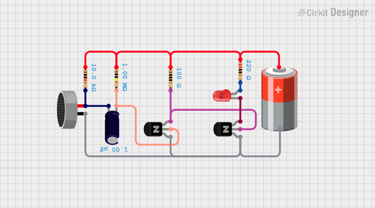
Circuit Documentation
Summary of the Circuit
This circuit appears to be a simple audio signal processing circuit that uses a condenser microphone to capture sound. The signal from the microphone is then amplified by a pair of NPN transistors. The amplified signal drives an LED, which may be used as a visual indicator of the sound level. The circuit also includes various resistors and a capacitor to stabilize and set the operating points of the transistors. A 5V battery provides the power supply for the entire circuit.
Component List
Condenser Microphone
- A transducer that converts sound into an electrical signal.
NPN Transistors (CBE)
- Two bipolar junction transistors used for amplifying the signal from the microphone.
LED: Two Pin (red)
- A light-emitting diode that serves as a visual indicator.
Resistors
- Four resistors with different resistance values (10kΩ, 220Ω, 100Ω, 1MΩ) used for biasing the transistors and limiting current.
Electrolytic Capacitor
- A capacitor with a capacitance of 1µF, likely used for coupling or filtering purposes.
5v Battery
- The power source for the circuit.
Wiring Details
Condenser Microphone
pin1is connected to the collector of one NPN transistor and the negative terminal of the 5V battery.pin2is connected to a 10kΩ resistor and the positive terminal of the electrolytic capacitor.
NPN Transistors (CBE)
- The collector of the first transistor is connected to the microphone and the collector of the second transistor.
- The base of the first transistor is connected to a 1MΩ resistor and the negative terminal of the electrolytic capacitor.
- The emitter of the first transistor is connected to the base of the second transistor and a 100Ω resistor.
- The collector of the second transistor is connected to the microphone and the collector of the first transistor.
- The base of the second transistor is connected to the emitter of the first transistor and a 100Ω resistor.
- The emitter of the second transistor is connected to the cathode of the LED.
LED: Two Pin (red)
cathodeis connected to the emitter of the second NPN transistor.anodeis connected to a 220Ω resistor.
Resistors
- The 10kΩ resistor is connected between the microphone and the positive terminal of the electrolytic capacitor.
- The 220Ω resistor is connected to the anode of the LED.
- The 100Ω resistor is connected between the emitter of the first transistor and the base of the second transistor.
- The 1MΩ resistor is connected between the base of the first transistor and the negative terminal of the electrolytic capacitor.
Electrolytic Capacitor
- The positive terminal is connected to the microphone and the 10kΩ resistor.
- The negative terminal is connected to the base of the first transistor and the 1MΩ resistor.
5v Battery
- The positive terminal is connected to the anode of the LED through a 220Ω resistor, and also to the 10kΩ, 100Ω, and 1MΩ resistors.
- The negative terminal is connected to the collector of both NPN transistors and the microphone.
Documented Code
There is no embedded code provided for this circuit as there are no microcontrollers or programmable components listed in the parts provided. Therefore, this section is not applicable to the current circuit documentation.