
ESP32-Based Water Level Monitoring System with Wi-Fi Connectivity and Multi-Color LED Indicators
View and Edit Project In Cirkit Designer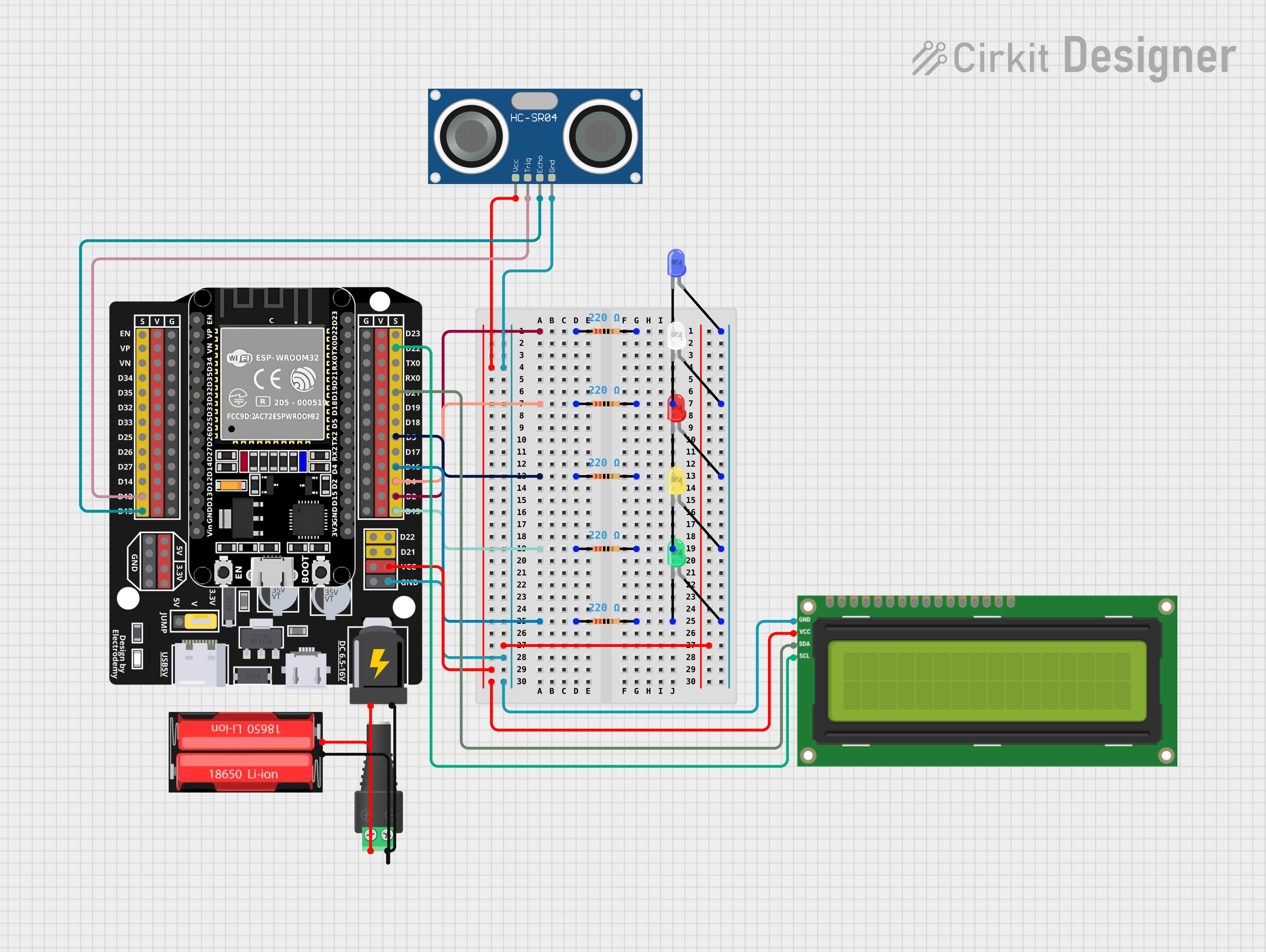
Circuit Documentation
Summary
The circuit is designed to monitor water levels using an ultrasonic sensor and display the status on an LCD screen. It also features a set of LEDs that indicate different water levels and connectivity status to a Blynk server over WiFi. The core of the circuit is an ESP32 Expansion Board, which controls the sensor, LEDs, and communicates with the Blynk server for remote monitoring.
Component List
ESP32 - Expansion Board
- A microcontroller board with WiFi capabilities, used as the central processing unit for the circuit.
LEDs (Red, Blue, Yellow, White, Green)
- Visual indicators for various water levels and WiFi connection status.
Resistors (220 Ohms)
- Current-limiting resistors for the LEDs to prevent damage from overcurrent.
HC-SR04 Ultrasonic Sensor
- A sensor used to measure the distance to the water surface, which is then translated into water level.
I2C LCD 16x2 Screen
- A display used to show the water level in centimeters and status messages.
18650 Li-Ion Battery
- A power source for the circuit.
2.1mm Barrel Jack with Terminal Block
- A connector for an external power supply to power the circuit.
Wiring Details
ESP32 - Expansion Board
- Digital pins D2, D4, D5, D15, D16 are connected to the current-limiting resistors for the LEDs.
- VCC pin is connected to the VCC of the ultrasonic sensor and the LCD screen.
- GND pin is connected to the GND of the ultrasonic sensor and the LCD screen.
- Digital pins D12 and D13 are connected to the TRIG and ECHO pins of the ultrasonic sensor, respectively.
- Digital pins D22 and D21 are connected to the SCL and SDA pins of the LCD screen, respectively.
- The
+and-pins are connected to the positive and negative terminals of the Li-Ion battery and the barrel jack.
LEDs (Red, Blue, Yellow, White, Green)
- The anodes of all LEDs are connected together.
- The cathodes of each LED are connected to their respective current-limiting resistors.
Resistors (220 Ohms)
- One end of each resistor is connected to a digital pin on the ESP32.
- The other end of each resistor is connected to the cathode of an LED.
HC-SR04 Ultrasonic Sensor
- VCC and GND pins are connected to the corresponding power supply pins on the ESP32.
- TRIG and ECHO pins are connected to digital pins D12 and D13 on the ESP32.
I2C LCD 16x2 Screen
- SCL and SDA pins are connected to digital pins D22 and D21 on the ESP32 for I2C communication.
- VCC (5V) and GND pins are connected to the corresponding power supply pins on the ESP32.
18650 Li-Ion Battery
- The positive and negative terminals are connected to the
+and-pins on the ESP32 and the barrel jack.
2.1mm Barrel Jack with Terminal Block
- POS and NEG terminals are connected to the
+and-pins on the ESP32 and the Li-Ion battery.
Documented Code
#define BLYNK_TEMPLATE_ID "TMPL6YXH7T8rC"
#define BLYNK_TEMPLATE_NAME "Water Level Monitoring System"
#define BLYNK_AUTH_TOKEN "T3o8N554EqsZLo7xWyT-Edl9GYJLK0bG"

// Include the library files
#include <LiquidCrystal_I2C.h>
#include <Wire.h>
#include <WiFiClient.h>
#include <BlynkSimpleEsp32.h>

#define LED_WIFI 2
#define LED_WHITE 4
#define LED_RED 5
#define LED_YELLOW 18
#define LED_GREEN 19
#define trig 12
#define echo 13

// Enter your tank max value (CM)
int MaxLevel = 20;

// Initialize the LCD display
LiquidCrystal_I2C lcd(0x27, 16, 2);

BlynkTimer timer;

// Enter your Auth token
char auth[] = BLYNK_AUTH_TOKEN;

// Enter your WIFI SSID and password
char ssid[] = "Eric23";
char pass[] = "eric2304";

void setup() {
  // Debug console
  Serial.begin(115200);
  Blynk.begin(auth, ssid, pass, "blynk.cloud", 80);
  lcd.init();
  lcd.backlight();
  pinMode(LED_WIFI, OUTPUT);
  pinMode(LED_WHITE, OUTPUT);
  pinMode(LED_RED, OUTPUT);
  pinMode(LED_YELLOW, OUTPUT);
  pinMode(LED_GREEN, OUTPUT);
  pinMode(trig, OUTPUT);
  pinMode(echo, INPUT);

  lcd.setCursor(0, 0);
  lcd.print("System");
  lcd.setCursor(4, 1);
  lcd.print("Loading..");
  delay(4000);
  lcd.clear();

  // Indicate WiFi connection status
  if (Blynk.connected()) {
    digitalWrite(LED_WIFI, HIGH);
  } else {
    digitalWrite(LED_WIFI, LOW);
  }
}

// Get the ultrasonic sensor values
void ultrasonic() {
  digitalWrite(trig, LOW);
  delayMicroseconds(4);
  digitalWrite(trig, HIGH);
  delayMicroseconds(10);
  digitalWrite(trig, LOW);
  long t = pulseIn(echo, HIGH);
  int distance = t / 29 / 2;

  Serial.println(distance);

  int blynkDistance = (distance - MaxLevel) * -1;
  if (distance <= MaxLevel) {
    Blynk.virtualWrite(V0, blynkDistance);
  } else {
    Blynk.virtualWrite(V0, 0);
  }
  lcd.setCursor(0, 0);
  lcd.print("WLevel:");
  lcd.setCursor(8, 0);
  lcd.print(distance);
  lcd.print(" cm");

  // Update LED status based on water level
  if (distance <= 5) {
    lcd.setCursor(0, 1);
    lcd.print("0-5cm  ");
    digitalWrite(LED_WHITE, HIGH);
    digitalWrite(LED_RED, LOW);
    digitalWrite(LED_YELLOW, LOW);
    digitalWrite(LED_GREEN, LOW);
  } else if (distance <= 10) {
    lcd.setCursor(0, 1);
    lcd.print("6-10cm ");
    digitalWrite(LED_WHITE, LOW);
    digitalWrite(LED_RED, HIGH);
    digitalWrite(LED_YELLOW, LOW);
    digitalWrite(LED_GREEN, LOW);
  } else if (distance <= 15) {
    lcd.setCursor(0, 1);
    lcd.print("11-15cm");
    digitalWrite(LED_WHITE, LOW);
    digitalWrite(LED_RED, LOW);
    digitalWrite(LED_YELLOW, HIGH);
    digitalWrite(LED_GREEN, LOW);
  } else if (distance <= 20) {
    lcd.setCursor(0, 1);
    lcd.print("16-20cm");
    digitalWrite(LED_WHITE, LOW);
    digitalWrite(LED_RED, LOW);
    digitalWrite(LED_YELLOW, LOW);
    digitalWrite(LED_GREEN, HIGH);
  } else {
    lcd.setCursor(0, 1);
    lcd.print("Overflow");
    digitalWrite(LED_WHITE, LOW);
    digitalWrite(LED_RED, LOW);
    digitalWrite(LED_YELLOW, LOW);
    digitalWrite(LED_GREEN, LOW);
  }
}

void loop() {
  ultrasonic();
  Blynk.run(); // Run the Blynk library

  // Update WiFi connection status LED
  if (Blynk.connected()) {
    digitalWrite(LED_WIFI, HIGH);
  } else {
    digitalWrite(LED_WIFI, LOW);
  }
}
This code is designed to run on the ESP32 Expansion Board. It initializes the WiFi connection, LCD screen, and sets up the pins for the LEDs and ultrasonic sensor. The ultrasonic function measures the water level and updates the LCD and LEDs accordingly. The Blynk library is used to send the water level data to a remote server for monitoring.