ESP32-Based Environmental Monitoring System with Servo Control
Circuit Documentation
Summary
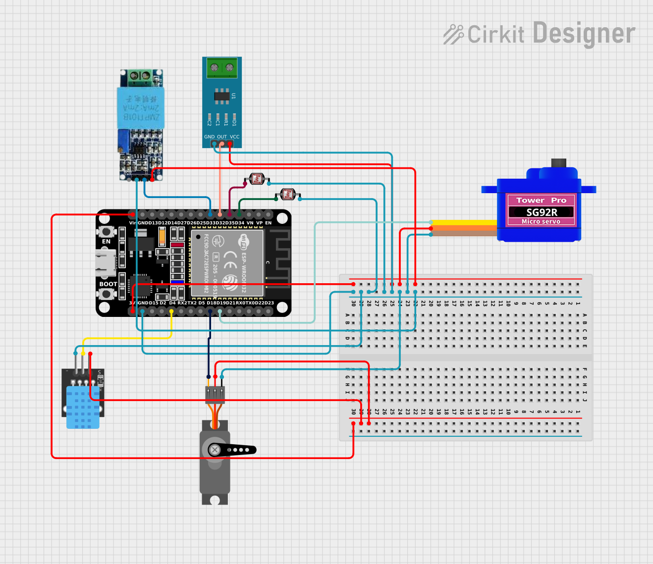
The circuit in question is designed to interface various sensors and actuators with an ESP32 microcontroller. The ESP32 serves as the central processing unit, reading data from sensors, including photocells (LDRs), a current sensor, a voltage sensor, and a DHT11 temperature and humidity sensor. It also controls two types of servomotors. The circuit is powered through the ESP32, which distributes power to the sensors and servomotors. Ground connections are shared across all components, establishing a common reference point for the circuit.
Component List
ESP32 (30 pin)
- Description: A microcontroller with Wi-Fi and Bluetooth capabilities, featuring a wide range of GPIO pins.
- Purpose: Acts as the central processing unit for the circuit, interfacing with sensors and controlling servomotors.
Servomotor SG92R
- Description: A small and lightweight servomotor suitable for applications that require precise control.
- Purpose: Receives PWM signals from the ESP32 to perform controlled movements.
Servo
- Description: A generic servomotor for controlled mechanical movements.
- Purpose: Operated by the ESP32 to perform tasks that require positioning or movement.
Current Sensor 5A
- Description: A sensor capable of measuring electrical current up to 5A.
- Purpose: Provides current measurements to the ESP32 for monitoring or control purposes.
Voltage Sensor
- Description: A sensor designed to measure electrical voltage.
- Purpose: Allows the ESP32 to monitor voltage levels in the circuit.
DHT11
- Description: A basic, low-cost digital temperature and humidity sensor.
- Purpose: Provides ambient temperature and humidity readings to the ESP32.
Photocell (LDR)
- Description: A light-dependent resistor whose resistance varies with light intensity.
- Purpose: Used for measuring light levels in the environment.
Wiring Details
ESP32 (30 pin)
- D34: Connected to Photocell (LDR) pin 0
- D35: Connected to Photocell (LDR) pin 0
- D32: Connected to Current Sensor 5A OUT
- D33: Connected to Voltage Sensor Out
- Vin: Connected to Servo VCC, DHT11 5V
- D19: Connected to Servomotor SG92R SIG
- D18: Connected to Servo PWM
- D4: Connected to DHT11 S
- GND: Common ground for all components
- 3V3: Power supply for Servomotor SG92R VCC, Current Sensor 5A VCC, Voltage Sensor Vcc
Servomotor SG92R
- SIG: Controlled by ESP32 D19
- VCC: Powered by ESP32 3V3
- GND: Connected to common ground
Servo
- PWM: Controlled by ESP32 D18
- VCC: Powered by ESP32 Vin
- GND: Connected to common ground
Current Sensor 5A
- OUT: Signal output to ESP32 D32
- VCC: Powered by ESP32 3V3
- GND: Connected to common ground
Voltage Sensor
- Out: Signal output to ESP32 D33
- Vcc: Powered by ESP32 3V3
- Ground: Connected to common ground
DHT11
- S: Signal pin connected to ESP32 D4
- 5V: Powered by ESP32 Vin
- GND: Connected to common ground
Photocell (LDR)
- pin 0: One connected to ESP32 D34, another to ESP32 D35
- pin 1: Both connected to common ground
Documented Code
No code has been provided for the microcontrollers in the circuit. The documentation of the code would typically include descriptions of the functions, initialization procedures, main loop, and any interrupt service routines. Since no code is available, this section cannot be completed.