ESP32 and ESP8266 NodeMCU Based Environmental Monitoring System with Motorized Fan Control
Circuit Documentation
Summary of the Circuit
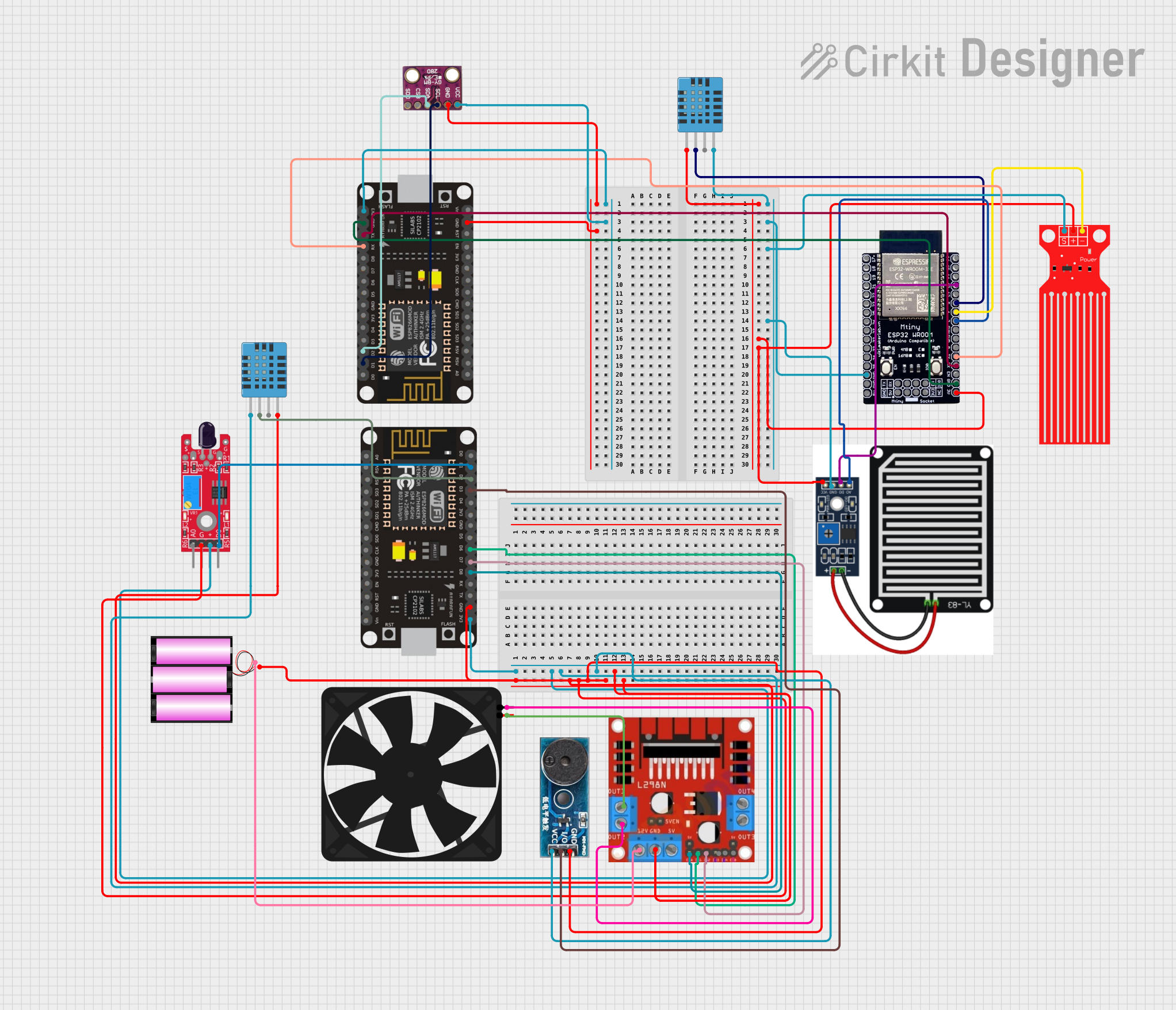
This circuit is designed to monitor environmental conditions and control a fan based on sensor inputs. It includes two microcontroller units (MCUs), the Mtiny ESP32 WROOM-32E and the ESP8266 NodeMCU, which are responsible for processing sensor data and controlling peripherals. The circuit features a variety of sensors including the DHT11 for humidity and temperature, the BMP280 for barometric pressure, a raindrop sensor, and a water level sensor. Additionally, a KY-026 flame sensor and a buzzer module are included for fire detection and alerting purposes. The L298N motor driver is used to control a fan, which can be activated based on the sensor inputs. Power is supplied by a 12V battery, and the circuit includes necessary connections for power distribution and signal communication between components.
Component List
Microcontrollers
- Mtiny ESP32 WROOM-32E: A powerful MCU with Wi-Fi and Bluetooth capabilities.
- ESP8266 NodeMCU: A Wi-Fi-enabled MCU with a wide range of GPIO pins.
Sensors
- DHT11 Humidity and Temperature Sensor: Measures ambient humidity and temperature.
- Raindrop Sensor: Detects raindrops or water flow on its surface.
- Water Level Sensor: Measures the level of water in a container or environment.
- BMP280: A sensor for measuring barometric pressure and temperature.
- KY-026 Flame Sensor: Detects the presence of a flame or fire.
Actuators
- L298N Motor Driver: Controls the speed and direction of motors.
- Fan: An electric fan controlled by the motor driver.
Alerting Devices
- Buzzer Module: Emits an audible alert when triggered.
Power Supply
- Battery 12V: Provides power to the circuit.
Wiring Details
Mtiny ESP32 WROOM-32E
- 3V3: Connected to the VDD of the DHT11 sensor, VCC of the Water Level Sensor, and VCC of the Raindrop sensor.
- GND: Common ground with the DHT11 sensor, Water Level Sensor, and Raindrop sensor.
- Pin 13: Connected to the D0 of the Raindrop sensor.
- Pin 5: Connected to the DATA of the DHT11 sensor.
- Pin 4: Connected to the GND of the Water Level Sensor.
- Pin 2: Connected to the A0 of the Raindrop sensor.
- TX: Connected to the RX of the ESP8266 NodeMCU.
- RX: Connected to the TX of the ESP8266 NodeMCU.
ESP8266 NodeMCU
- 3V3: Connected to the VCC of the BMP280 sensor.
- GND: Common ground with the BMP280 sensor.
- RX: Connected to the TX of the Mtiny ESP32 WROOM-32E.
- TX: Connected to the RX of the Mtiny ESP32 WROOM-32E.
- D1: Connected to the SCL of the BMP280 sensor.
- D2: Connected to the SDA of the BMP280 sensor.
DHT11 Humidity and Temperature Sensor
- VDD: Connected to the 3V3 of the Mtiny ESP32 WROOM-32E.
- DATA: Connected to Pin 5 of the Mtiny ESP32 WROOM-32E.
- GND: Common ground with the Mtiny ESP32 WROOM-32E.
Raindrop Sensor
- VCC: Connected to the 3V3 of the Mtiny ESP32 WROOM-32E.
- D0: Connected to Pin 13 of the Mtiny ESP32 WROOM-32E.
- A0: Connected to Pin 2 of the Mtiny ESP32 WROOM-32E.
- GND: Common ground with the Mtiny ESP32 WROOM-32E.
Water Level Sensor
- VCC: Connected to the 3V3 of the Mtiny ESP32 WROOM-32E.
- SIG: Connected to Pin 4 of the Mtiny ESP32 WROOM-32E.
- GND: Common ground with the Mtiny ESP32 WROOM-32E.
BMP280
- VCC: Connected to the 3V3 of the ESP8266 NodeMCU.
- GND: Common ground with the ESP8266 NodeMCU.
- SCL: Connected to the D1 of the ESP8266 NodeMCU.
- SDA: Connected to the D2 of the ESP8266 NodeMCU.
L298N Motor Driver
- VCC: Connected to the + of the 12V battery.
- GND: Common ground with the 12V battery.
- OUT 1: Connected to the 5V of the Fan.
- OUT 2: Connected to the GND of the Fan.
Fan
- 5V: Connected to the OUT 1 of the L298N motor driver.
- GND: Connected to the OUT 2 of the L298N motor driver.
KY-026 Flame Sensor
- VCC: Connected to the 3V3 of the ESP8266 NodeMCU.
- GND: Common ground with the ESP8266 NodeMCU.
- DO: Connected to the D1 of the ESP8266 NodeMCU.
Buzzer Module
- Vcc: Connected to the 3V3 of the ESP8266 NodeMCU.
- GND: Common ground with the ESP8266 NodeMCU.
- I/O: Connected to the D3 of the ESP8266 NodeMCU.
Battery 12V
- +: Connected to the VCC of the L298N motor driver.
- -: Common ground with the L298N motor driver.
Documented Code
No code has been provided for the microcontrollers in the circuit. To fully implement the functionality of this circuit, embedded code for the Mtiny ESP32 WROOM-32E and the ESP8266 NodeMCU would be required. The code would handle sensor data acquisition, processing, and control of the fan and buzzer based on the sensor inputs.