
Circuit Documentation
Summary of the Circuit
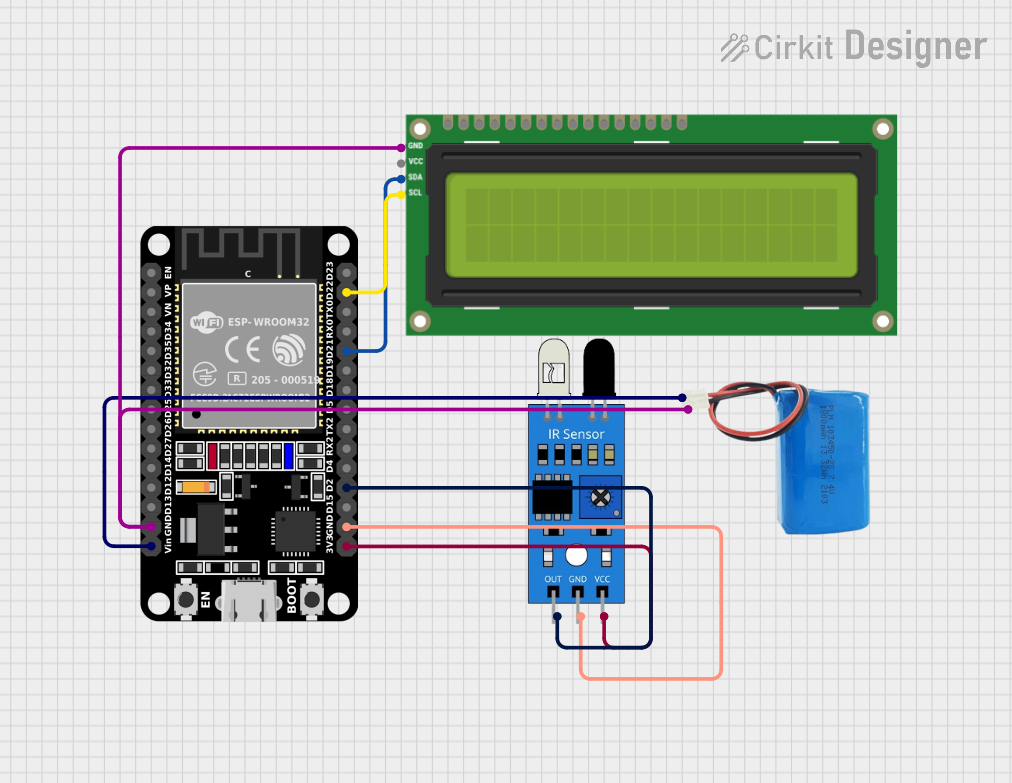
This circuit integrates an ESP32 microcontroller with a 16x2 I2C LCD screen and an infrared (IR) sensor. The ESP32 is responsible for controlling the operation of the circuit, including reading the status of the IR sensor and displaying the status on the LCD screen. The IR sensor detects the presence of objects, and the LCD provides a visual output of the sensor's status. The circuit is powered by a 5V battery.
Component List
ESP32 (30 pin)
- Description: A microcontroller with WiFi and Bluetooth capabilities, featuring a wide range of GPIO pins.
- Purpose: Acts as the central processing unit of the circuit, interfacing with the IR sensor and the I2C LCD screen to display sensor data.
I2C LCD 16x2 Screen
- Description: A liquid crystal display that can show 16 characters per line across 2 lines, with an I2C interface for communication.
- Purpose: To display the status of the IR sensor as detected by the ESP32.
5V Battery
- Description: A power source providing a 5V supply.
- Purpose: To power the ESP32 and other components in the circuit.
IR Sensor
- Description: A sensor that detects infrared light, commonly used to detect the presence or absence of objects.
- Purpose: To sense the presence of objects and provide this information to the ESP32.
Wiring Details
ESP32 (30 pin)
- GND: Connected to the ground pins of the I2C LCD screen, the IR sensor, and the negative terminal of the 5V battery.
- Vin: Connected to the positive terminal of the 5V battery.
- D22 (SCL): Connected to the SCL pin of the I2C LCD screen.
- D21 (SDA): Connected to the SDA pin of the I2C LCD screen.
- D2: Connected to the output pin of the IR sensor.
- 3V3: Connected to the VCC pin of the IR sensor.
I2C LCD 16x2 Screen
- SCL: Connected to the D22 pin of the ESP32.
- SDA: Connected to the D21 pin of the ESP32.
- GND: Connected to the ground pin of the ESP32.
- VCC (5V): Can be connected to a 5V supply if needed (not specified in the net list).
5V Battery
- Positive: Connected to the Vin pin of the ESP32.
- Negative: Connected to the GND pin of the ESP32.
IR Sensor
- Out: Connected to the D2 pin of the ESP32.
- Gnd: Connected to the GND pin of the ESP32.
- Vcc: Connected to the 3V3 pin of the ESP32.
Documented Code
/*
 * ESP32 Interface with I2C LCD and IR Sensor
 * This code reads the status of an IR sensor and displays it on an I2C LCD.
 */

#include <Wire.h>
#include <LiquidCrystal_I2C.h>

// Define the I2C address for the LCD
#define I2C_ADDR 0x27
#define LCD_COLUMNS 16
#define LCD_ROWS 2

// Initialize the LCD
LiquidCrystal_I2C lcd(I2C_ADDR, LCD_COLUMNS, LCD_ROWS);

// Define the IR sensor pin
const int irSensorPin = 2;

void setup() {
  // Initialize the LCD
  lcd.begin();
  lcd.backlight();
  lcd.setCursor(0, 0);
  lcd.print("IR Sensor Status:");

  // Initialize the IR sensor pin
  pinMode(irSensorPin, INPUT);
}

void loop() {
  // Read the IR sensor value
  int irValue = digitalRead(irSensorPin);

  // Display the IR sensor status on the LCD
  lcd.setCursor(0, 1);
  if (irValue == HIGH) {
    lcd.print("Object Detected ");
  } else {
    lcd.print("No Object       ");
  }

  // Small delay to avoid flickering
  delay(200);
}
Filename: sketch.ino
Description: The code initializes the I2C LCD and configures the IR sensor pin as an input. In the main loop, it reads the IR sensor value and updates the LCD with the status of object detection. If an object is detected, it displays "Object Detected"; otherwise, it shows "No Object". A small delay is included to prevent display flickering.