
Arduino UNO Based Pulse Oximeter and Temperature Monitoring System with Wi-Fi Notification
View and Edit Project In Cirkit Designer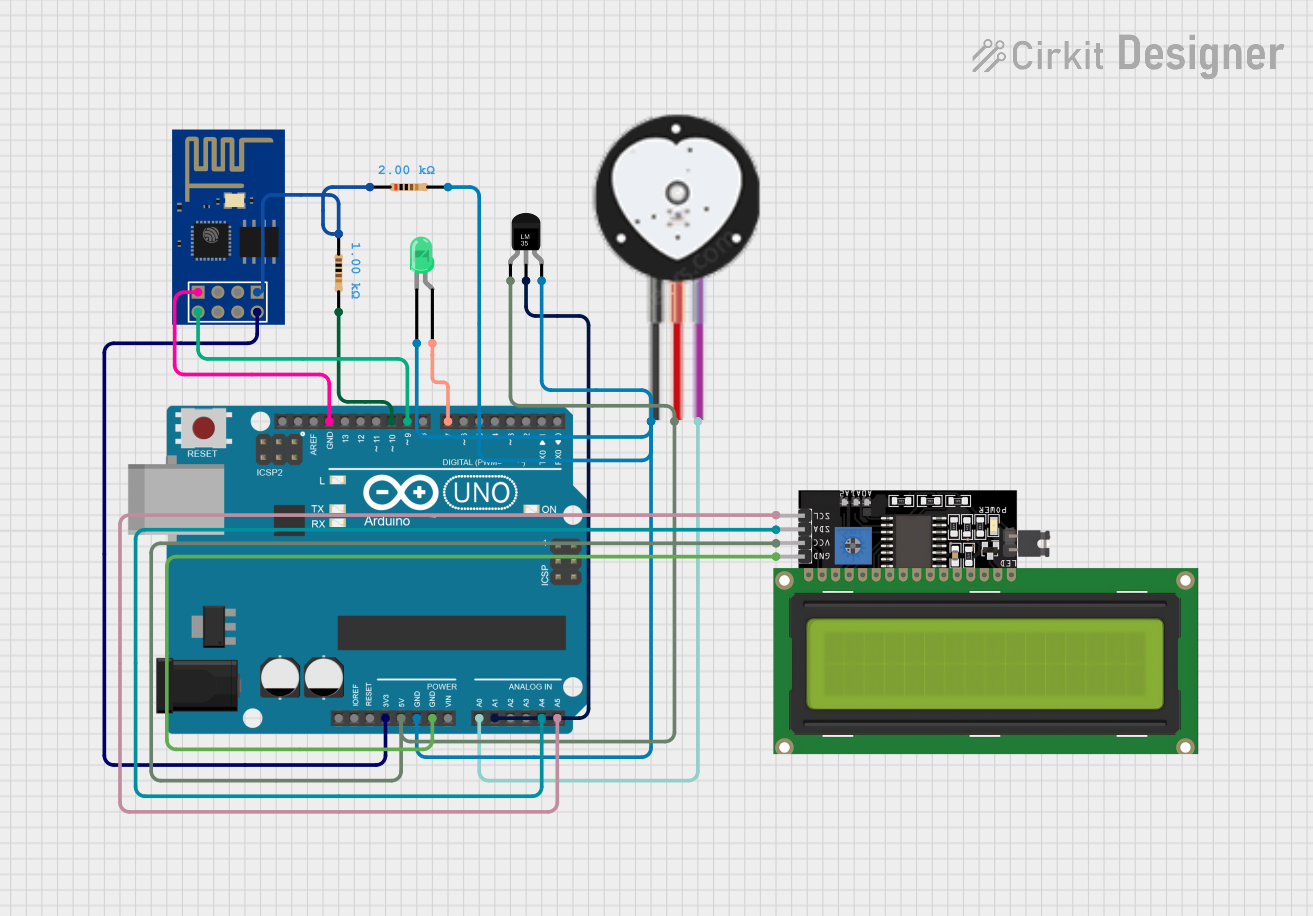
Circuit Documentation
Summary
This circuit is designed to monitor vital health parameters, specifically heart pulse rate and body temperature, and display the readings on an LCD. It also features an alert system that sends an SMS notification via the ESP8266 WiFi module if the temperature exceeds a certain threshold or if the pulse rate drops below a set limit. The Arduino UNO serves as the central microcontroller, interfacing with a heart pulse sensor, a temperature sensor (LM35), an ESP8266 WiFi module for communication, and an LCD display for real-time data output. An LED indicator is included to provide a visual alert.
Component List
Heart Pulse Sensor
- Pins: GND, VCC, SIGNAL
- Description: Used to measure the pulse rate of an individual.
Arduino UNO
- Pins: UNUSED, IOREF, Reset, 3.3V, 5V, GND, Vin, A0-A5, SCL, SDA, AREF, D0-D13
- Description: The main microcontroller board that processes sensor data and controls the operation of the circuit.
Temperature Sensor (LM35)
- Pins: +Vs, Vout, GND
- Description: Measures the ambient temperature.
ESP8266 ESP-01 WiFi Module
- Pins: TXD, CH_PD, RST, VCC, GND, GPIO_2, GPIO_0, RXD
- Description: Provides WiFi connectivity and enables the sending of SMS notifications.
LED: Two Pin (green)
- Pins: cathode, anode
- Description: Acts as a visual indicator for alerts.
LCD Display 16x4 I2C
- Pins: SCL, SDA, VCC, GND
- Description: Displays the temperature and pulse rate readings.
Resistor (1k Ohm)
- Pins: pin1, pin2
- Properties: Resistance: 1000 Ohms
Resistor (2k Ohm)
- Pins: pin1, pin2
- Properties: Resistance: 2000 Ohms
Wiring Details
Heart Pulse Sensor
- GND connected to Arduino UNO GND
- VCC connected to Arduino UNO 5V
- SIGNAL connected to Arduino UNO A0
Arduino UNO
- 3.3V connected to ESP8266 ESP-01 WiFi Module VCC
- 5V connected to Heart Pulse Sensor VCC, Temperature Sensor (LM35) +Vs, and LCD Display 16x4 I2C VCC
- GND connected to Heart Pulse Sensor GND, Temperature Sensor (LM35) GND, LED (green) cathode, LCD Display 16x4 I2C GND, ESP8266 ESP-01 WiFi Module GND
- A0 connected to Heart Pulse Sensor SIGNAL
- A1 connected to Temperature Sensor (LM35) Vout
- A4 connected to LCD Display 16x4 I2C SDA
- A5 connected to LCD Display 16x4 I2C SCL
- D7 connected to LED (green) anode
- D9 connected to ESP8266 ESP-01 WiFi Module TXD
- D10 connected to ESP8266 ESP-01 WiFi Module RXD through a 1k Ohm resistor
Temperature Sensor (LM35)
- +Vs connected to Arduino UNO 5V
- Vout connected to Arduino UNO A1
- GND connected to Arduino UNO GND
ESP8266 ESP-01 WiFi Module
- TXD connected to Arduino UNO D9
- RXD connected to Arduino UNO D10 through a 2k Ohm resistor
- VCC connected to Arduino UNO 3.3V
- GND connected to Arduino UNO GND
LED: Two Pin (green)
- anode connected to Arduino UNO D7
- cathode connected to Arduino UNO GND
LCD Display 16x4 I2C
- SCL connected to Arduino UNO A5
- SDA connected to Arduino UNO A4
- VCC connected to Arduino UNO 5V
- GND connected to Arduino UNO GND
Resistor (1k Ohm)
- pin1 connected to ESP8266 ESP-01 WiFi Module RXD
- pin2 connected to Arduino UNO D10
Resistor (2k Ohm)
- pin1 connected to ESP8266 ESP-01 WiFi Module RXD
- pin2 connected to Arduino UNO GND
Documented Code
/*
 * Pulse Oximeter and Temperature Sensor with SMS Notification
 * This code reads data from a heart pulse sensor and a temperature sensor.
 * If the body temperature exceeds a threshold or the oxygen level drops
 * below a threshold, an SMS notification is sent via the ESP8266 WiFi module.
 */

#include <Wire.h>
#include <LiquidCrystal_I2C.h>
#include <SoftwareSerial.h>

// Pin definitions
const int pulsePin = A0;
const int tempPin = A1;
const int ledPin = 7;
const int espTx = 9;
const int espRx = 10;

// Thresholds
const float tempThreshold = 37.5; // Celsius
const int pulseThreshold = 60; // BPM

// LCD setup
LiquidCrystal_I2C lcd(0x27, 16, 4);

// ESP8266 setup
SoftwareSerial espSerial(espRx, espTx);

void setup() {
  // Initialize serial communication
  Serial.begin(9600);
  espSerial.begin(115200);

  // Initialize LCD
  lcd.begin();
  lcd.backlight();

  // Initialize LED pin
  pinMode(ledPin, OUTPUT);
  digitalWrite(ledPin, LOW);

  // Initialize ESP8266
  sendCommand("AT", 1000);
  sendCommand("AT+CWMODE=1", 1000);
  sendCommand("AT+CWJAP=\"yourSSID\",\"yourPASSWORD\"", 5000);
}

void loop() {
  // Read pulse sensor data
  int pulseValue = analogRead(pulsePin);
  int pulseBPM = map(pulseValue, 0, 1023, 0, 150); // Example mapping

  // Read temperature sensor data
  int tempValue = analogRead(tempPin);
  float temperature = (tempValue / 1024.0) * 5.0 * 100.0;

  // Display data on LCD
  lcd.setCursor(0, 0);
  lcd.print("Temp: ");
  lcd.print(temperature);
  lcd.print(" C");
  lcd.setCursor(0, 1);
  lcd.print("Pulse: ");
  lcd.print(pulseBPM);
  lcd.print(" BPM");

  // Check thresholds and send SMS if needed
  if (temperature > tempThreshold || pulseBPM < pulseThreshold) {
    digitalWrite(ledPin, HIGH);
    sendSMS("Alert! Temp: " + String(temperature) + " C, Pulse: " + String(pulseBPM) + " BPM");
  } else {
    digitalWrite(ledPin, LOW);
  }

  delay(1000); // Wait for 1 second before next reading
}

void sendCommand(String command, int timeout) {
  espSerial.println(command);
  long int time = millis();
  while ((time + timeout) > millis()) {
    while (espSerial.available()) {
      char c = espSerial.read();
      Serial.print(c);
    }
  }
}

void sendSMS(String message) {
  sendCommand("AT+CMGF=1", 1000); // Set SMS mode
  sendCommand("AT+CMGS=\"+1234567890\"", 1000); // Replace with your phone number
  espSerial.print(message);
  espSerial.write(26); // ASCII code for CTRL+Z
}
This code is designed to be uploaded to the Arduino UNO microcontroller. It initializes the sensors, reads their data, displays the readings on the LCD, and sends an SMS alert if the readings are outside the set thresholds. The sendCommand function is used to communicate with the ESP8266 module, and the sendSMS function is used to send the SMS message.