
Circuit Documentation
Summary
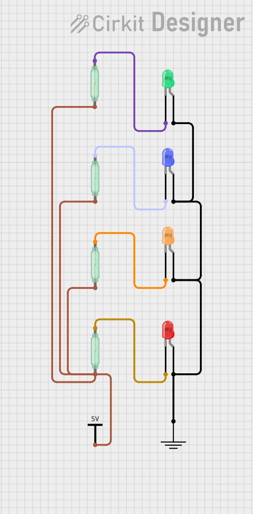
This circuit consists of multiple reed switches and LEDs of various colors. The reed switches are used to control the LEDs, which light up when the corresponding reed switch is activated. The circuit is powered by a Vcc source and grounded appropriately.
Component List
Reed Switch
- Description: A magnetic switch that closes in the presence of a magnetic field.
- Pins: pin 1, pin 2
LED: Two Pin (green)
- Description: A green light-emitting diode.
- Pins: cathode, anode
LED: Two Pin (blue)
- Description: A blue light-emitting diode.
- Pins: cathode, anode
LED: Two Pin (orange)
- Description: An orange light-emitting diode.
- Pins: cathode, anode
LED: Two Pin (red)
- Description: A red light-emitting diode.
- Pins: cathode, anode
GND
- Description: Ground connection.
- Pins: GND
Vcc
- Description: Power supply connection.
- Pins: Vcc
Wiring Details
Reed Switch 1
- pin 1: Connected to Vcc
- pin 2: Connected to the cathode of the green LED
Reed Switch 2
- pin 1: Connected to Vcc
- pin 2: Connected to the cathode of the blue LED
Reed Switch 3
- pin 1: Connected to Vcc
- pin 2: Connected to the cathode of the red LED
Reed Switch 4
- pin 1: Connected to Vcc
- pin 2: Connected to the cathode of the orange LED
LED: Two Pin (green)
- cathode: Connected to pin 2 of Reed Switch 1
- anode: Connected to GND
LED: Two Pin (blue)
- cathode: Connected to pin 2 of Reed Switch 2
- anode: Connected to GND
LED: Two Pin (orange)
- cathode: Connected to pin 2 of Reed Switch 4
- anode: Connected to GND
LED: Two Pin (red)
- cathode: Connected to pin 2 of Reed Switch 3
- anode: Connected to GND
GND
- GND: Connected to the anodes of all LEDs
Vcc
- Vcc: Connected to pin 1 of all Reed Switches
Code
No microcontroller code is provided for this circuit.
This documentation provides a comprehensive overview of the circuit, including a summary, detailed component list, wiring details, and code section. Each component is described, and its connections are clearly outlined to ensure proper assembly and understanding of the circuit.