
Arduino Mega 2560-Based Robotic Automation System with Ultrasonic Sensing and GPS
View and Edit Project In Cirkit Designer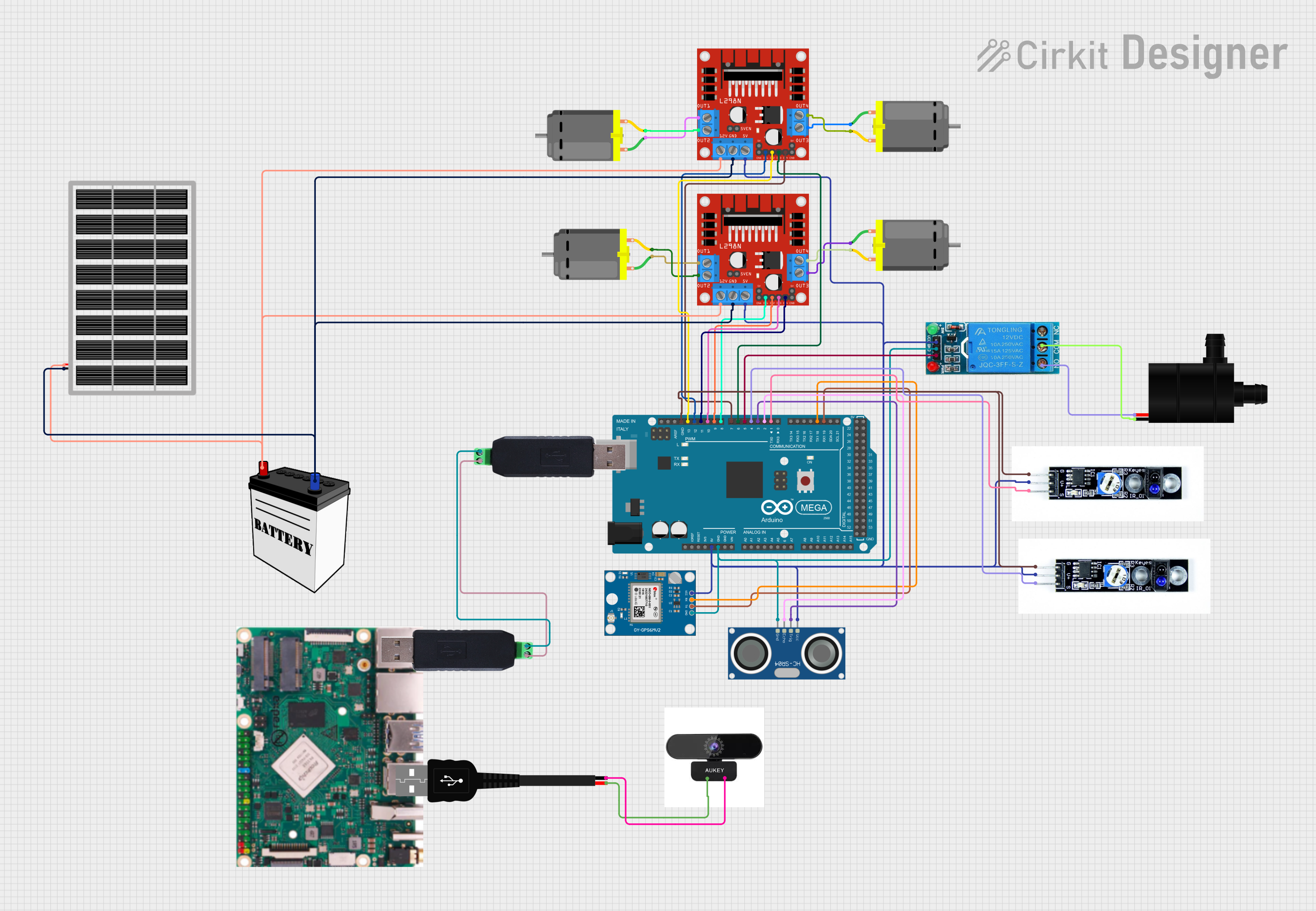
Circuit Documentation
Summary
The circuit in question is designed to interface various sensors, actuators, and modules with an Arduino Mega 2560 microcontroller. The circuit includes an ultrasonic sensor (HC-SR04), a GPS module (Neo 6M), line tracking sensors, a DC motor driver (L298N), a single-channel relay, multiple DC motors, a water pump, and power supply components such as a 12V battery and a solar panel. Communication between devices is facilitated by RS485 to USB converters. Additionally, a camera USB input is powered through a USB male 2-pin connection.
Component List
HC-SR04 Ultrasonic Sensor
- Pins: VCC, TRIG, ECHO, GND
- Description: This sensor is used for measuring distances using ultrasonic waves.
12V Battery
- Pins: VCC, GND
- Description: Provides the main power source for the circuit.
Arduino Mega 2560
- Pins: Multiple digital and analog I/O pins, power, and ground pins.
- Description: The central microcontroller unit for controlling and interfacing with all other components.
L298N DC Motor Driver
- Pins: OUT1, OUT2, 12V, GND, 5V, OUT3, OUT4, ENA, IN1, IN2, IN3, IN4, ENB
- Description: Used to control the direction and speed of DC motors.
12V Single Channel Relay
- Pins: NC, COM, NO, IN, GND, VCC
- Description: Acts as an electrically operated switch to control the water pump.
DC Motor
- Pins: pin 1, pin 2
- Description: Converts electrical energy into mechanical motion.
Water Pump
- Pins: VCC, GND
- Description: Used to pump water when activated by the relay.
Neo 6M GPS Module
- Pins: GND, TX, RX, VCC
- Description: Provides location data to the microcontroller.
Rock Pi (No pins listed)
- Description: A single-board computer, not directly interfaced in this circuit.
RS485 to USB Converter
- Pins: A/TX, B/RX
- Description: Facilitates RS485 communication over USB.
USB Male 2 Pin Connection
- Pins: Negative -, Positive +
- Description: Provides a USB power connection for the camera.
Camera USB Input
- Pins: negative, positive
- Description: Receives power from the USB connection.
Solar Panel
- Pins: gnd, vcc
- Description: An alternative power source that can charge the battery or power the circuit directly.
Line Tracking Sensor
- Pins: GND, VCC, SIG
- Description: Detects and follows a line on the ground.
Wiring Details
HC-SR04 Ultrasonic Sensor
- VCC: Connected to 5V power net.
- TRIG: Connected to Arduino Mega 2560 pin D3 PWM.
- ECHO: Connected to Arduino Mega 2560 pin D2 PWM.
- GND: Connected to ground net.
12V Battery
- VCC: Connected to 12V power net.
- GND: Connected to ground net.
Arduino Mega 2560
- 5V: Connected to 5V power net.
- GND: Connected to ground net.
- D2 PWM: Connected to HC-SR04 ECHO pin.
- D3 PWM: Connected to HC-SR04 TRIG pin.
- D19/RX1: Connected to Neo 6M GPS Module TX pin.
- D18/TX1: Connected to Neo 6M GPS Module RX pin.
- D1 TX0: Connected to Line Tracking Sensor SIG pin (instance 0768b8b2-78cd-4fa8-94e5-a14d2c1dbb3d).
- D4 PWM: Connected to Line Tracking Sensor SIG pin (instance 6a6e0563-e6b5-4898-942d-c9b9b081d46a).
- D5 PWM: Connected to 12V Single Channel Relay IN pin.
- D6 PWM: Connected to L298N DC motor driver IN3 pin (instance 8c8f2e21-c8ed-4337-802d-9c635ae01e6c).
- D7 PWM: Connected to L298N DC motor driver IN4 pin (instance 8c8f2e21-c8ed-4337-802d-9c635ae01e6c).
- D8 PWM: Connected to L298N DC motor driver IN1 pin (instance f8d79c62-d198-4654-9e8a-779e9c3bf133).
- D9 PWM: Connected to L298N DC motor driver IN2 pin (instance f8d79c62-d198-4654-9e8a-779e9c3bf133).
- D10 PWM: Connected to L298N DC motor driver IN3 pin (instance f8d79c62-d198-4654-9e8a-779e9c3bf133).
- D11 PWM: Connected to L298N DC motor driver IN4 pin (instance f8d79c62-d198-4654-9e8a-779e9c3bf133).
- D12 PWM: Connected to L298N DC motor driver IN1 pin (instance 8c8f2e21-c8ed-4337-802d-9c635ae01e6c).
- D13 PWM: Connected to L298N DC motor driver IN2 pin (instance 8c8f2e21-c8ed-4337-802d-9c635ae01e6c).
L298N DC Motor Driver (Instance 8c8f2e21-c8ed-4337-802d-9c635ae01e6c)
- 5V: Connected to 5V power net.
- 12V: Connected to 12V power net.
- GND: Connected to ground net.
- IN1: Connected to Arduino Mega 2560 pin D12 PWM.
- IN2: Connected to Arduino Mega 2560 pin D13 PWM.
- IN3: Connected to Arduino Mega 2560 pin D6 PWM.
- IN4: Connected to Arduino Mega 2560 pin D7 PWM.
- OUT1: Connected to DC Motor pin 1 (instance 81563cef-a912-4105-b236-38b55656291a).
- OUT2: Connected to DC Motor pin 2 (instance 81563cef-a912-4105-b236-38b55656291a).
- OUT3: Connected to DC Motor pin 1 (instance 652dac88-3477-4d5d-be6e-315dac8802de).
- OUT4: Connected to DC Motor pin 2 (instance 652dac88-3477-4d5d-be6e-315dac8802de).
L298N DC Motor Driver (Instance f8d79c62-d198-4654-9e8a-779e9c3bf133)
- 5V: Connected to 5V power net.
- 12V: Connected to 12V power net.
- GND: Connected to ground net.
- IN1: Connected to Arduino Mega 2560 pin D8 PWM.
- IN2: Connected to Arduino Mega 2560 pin D9 PWM.
- IN3: Connected to Arduino Mega 2560 pin D10 PWM.
- IN4: Connected to Arduino Mega 2560 pin D11 PWM.
- OUT1: Connected to DC Motor pin 1 (instance 218f8d1e-9012-4937-8e21-90155855d2a3).
- OUT2: Connected to DC Motor pin 2 (instance 218f8d1e-9012-4937-8e21-90155855d2a3).
- OUT3: Connected to DC Motor pin 1 (instance 9ccf7c54-b4b8-4e54-b532-78ee2addd3f0).
- OUT4: Connected to DC Motor pin 2 (instance 9ccf7c54-b4b8-4e54-b532-78ee2addd3f0).
12V Single Channel Relay
- VCC: Connected to 5V power net.
- GND: Connected to ground net.
- IN: Connected to Arduino Mega 2560 pin D5 PWM.
- COM: Connected to Water Pump GND pin.
- NO: Connected to Water Pump VCC pin.
DC Motors
- Each DC Motor has two pins (pin 1 and pin 2) connected to the corresponding OUT pins of the L298N DC motor drivers.
Water Pump
- VCC: Connected to 12V Single Channel Relay NO pin.
- GND: Connected to 12V Single Channel Relay COM pin.
Neo 6M GPS Module
- VCC: Connected to 5V power net.
- GND: Connected to ground net.
- TX: Connected to Arduino Mega 2560 pin D19/RX1.
- RX: Connected to Arduino Mega 2560 pin D18/TX1.
Line Tracking Sensors
- VCC: