
Arduino Mega 2560 RFID Servo Control System with LCD Feedback
View and Edit Project In Cirkit Designer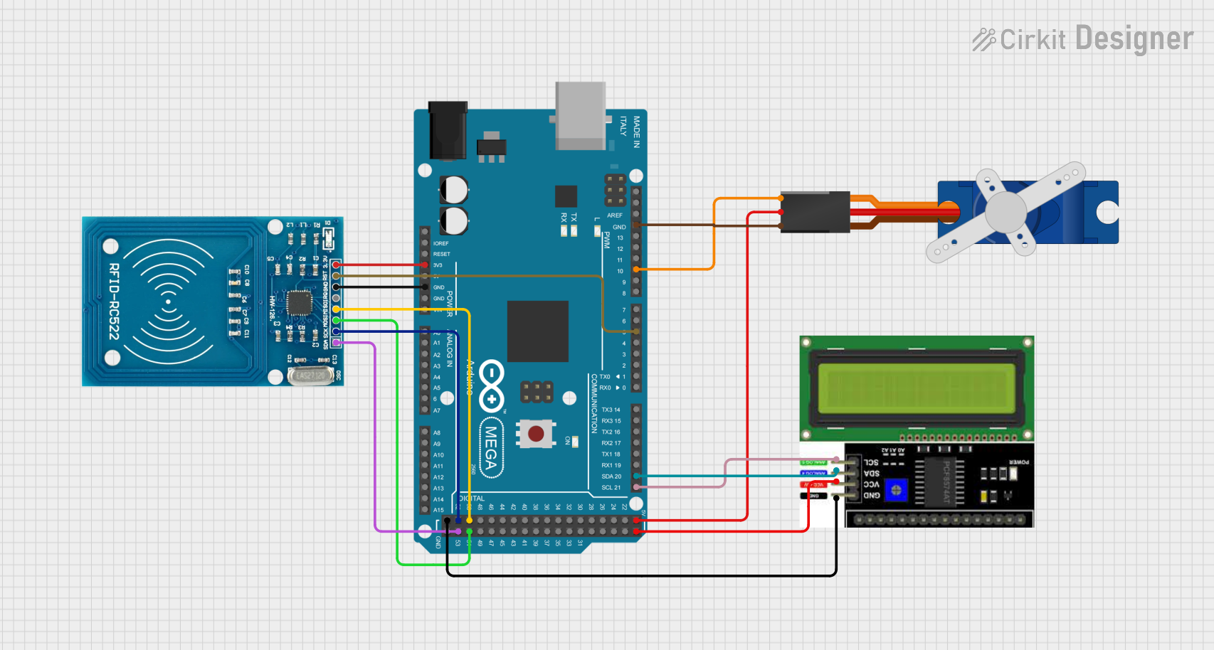
Circuit Documentation
Summary of the Circuit
This circuit is designed to interface an Arduino Mega 2560 with an RFID-RC522 module, a Tower Pro SG90 servo motor, and an LCD I2C display. The Arduino Mega 2560 serves as the central processing unit, controlling the servo motor based on RFID card detection and communicating with the LCD display via the I2C protocol. The RFID-RC522 module reads RFID cards and communicates with the Arduino over the SPI interface. The servo motor is controlled through one of the PWM-capable digital pins on the Arduino. The LCD display is used to provide visual feedback and is connected via the I2C bus.
Component List
Tower Pro SG90 Servo
- Description: A small and lightweight servo motor suitable for a variety of applications.
- Pins: Signal, +5V, GND
LCD I2C Display
- Description: A liquid crystal display that uses the I2C communication protocol for displaying text and characters.
- Pins: GND, VCC, SDA, SCL
Arduino Mega 2560
- Description: A microcontroller board based on the ATmega2560, with a large number of IO pins, including digital, analog, PWM, and dedicated SPI and I2C pins.
- Pins: Multiple digital and analog pins, including dedicated SDA and SCL pins for I2C communication, and pins for SPI communication.
RFID-RC522
- Description: An RFID reader/writer module that operates at 13.56 MHz and communicates with the Arduino via the SPI interface.
- Pins: VCC (3.3V), RST, GND, IRQ, MISO, MOSI, SCK, SDA
Wiring Details
Tower Pro SG90 Servo
- Signal: Connected to Arduino Mega 2560 pin D10 PWM
- +5V: Connected to Arduino Mega 2560 pin 5V
- GND: Connected to Arduino Mega 2560 pin GND
LCD I2C Display
- GND: Connected to Arduino Mega 2560 pin GND
- VCC: Connected to Arduino Mega 2560 pin 5V
- SDA: Connected to Arduino Mega 2560 pin D20/SDA
- SCL: Connected to Arduino Mega 2560 pin D21/SCL
RFID-RC522
- VCC (3.3V): Connected to Arduino Mega 2560 pin 3V3
- RST: Connected to Arduino Mega 2560 pin D5 PWM
- GND: Connected to Arduino Mega 2560 pin GND
- IRQ: Not connected
- MISO: Connected to Arduino Mega 2560 pin D50
- MOSI: Connected to Arduino Mega 2560 pin D51
- SCK: Connected to Arduino Mega 2560 pin D52
- SDA: Connected to Arduino Mega 2560 pin D53
Documented Code
#include <SPI.h>
#include <MFRC522.h>
#include <Servo.h>

#define SS_PIN 53
#define RST_PIN 5
#define SERVO_PIN 10

MFRC522 rfid(SS_PIN, RST_PIN); // Instance of the RFID-RC522 class
Servo myServo; // Instance of the Servo class

void setup() {
  Serial.begin(9600); // Start serial communication at 9600 baud
  SPI.begin(); // Initialize SPI bus
  rfid.PCD_Init();  // Initialize the MFRC522 reader
  myServo.attach(SERVO_PIN);  // Attach the servo to pin 10
  myServo.write(0);  // Start with the servo at 0 degrees
  Serial.println("Place your RFID card near the reader...");
}

void loop() {
  // Look for new cards
  if (rfid.PICC_IsNewCardPresent() && rfid.PICC_ReadCardSerial()) {
    Serial.print("Card UID: ");
    for (byte i = 0; i < rfid.uid.size; i++) {
      Serial.print(rfid.uid.uidByte[i] < 0x10 ? " 0" : " ");
      Serial.print(rfid.uid.uidByte[i], HEX);
    }
    Serial.println();

    // Display message for successful scan
    Serial.println("RC522 RFID Access Control");

    // Rotate the servo to 90 degrees
    myServo.write(90);
    delay(1000);  // Keep the servo at 90 degrees for 1 second

    // Reset the servo back to 0 degrees
    myServo.write(0);

    delay(2000);  // Delay to allow time between readings
  }

  // Stop reading the card
  rfid.PICC_HaltA();
}
This code initializes the RFID-RC522 module and the servo motor, and sets up the Arduino to read RFID cards. When a card is detected, it prints the card's UID to the serial monitor, rotates the servo to 90 degrees, then resets it back to 0 degrees after a short delay.