Cirkit Designer
Your all-in-one circuit design IDE
Home /
Project Documentation
Arduino UNO-Based Environmental Monitoring System with Motion Detection and Light Sensing
Circuit Documentation
Summary of the Circuit
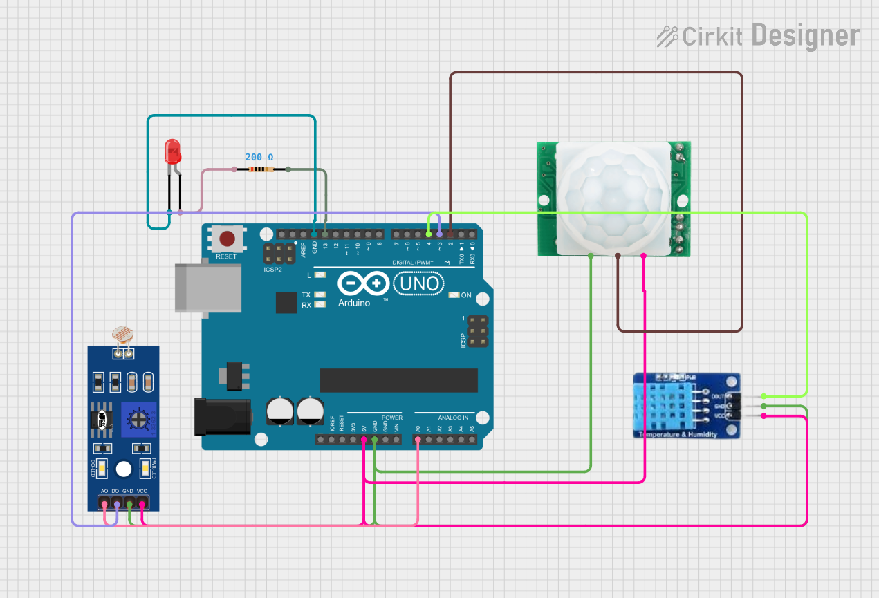
This circuit is designed around an Arduino UNO microcontroller, which serves as the central processing unit. The circuit includes a variety of sensors and output devices, including an LDR (Light Dependent Resistor), a DHT11 temperature and humidity sensor, an HC-SR501 motion sensor, and an LED with a series resistor. The Arduino UNO is responsible for interfacing with these components, processing sensor data, and controlling the LED based on certain conditions.
Component List
Arduino UNO
- Description: A microcontroller board based on the ATmega328P.
- Purpose: Acts as the central processing unit for the circuit, interfacing with sensors and controlling outputs.
Resistor (200 Ohms)
- Description: A passive two-terminal electrical component that implements electrical resistance as a circuit element.
- Purpose: Limits current to the LED to prevent damage.
HC-SR501 Motion Sensor
- Description: A PIR sensor module that detects motion by measuring changes in the infrared levels emitted by surrounding objects.
- Purpose: Provides motion detection capabilities to the circuit.
LED: Two Pin (Red)
- Description: A two-pin light-emitting diode that emits red light when powered.
- Purpose: Acts as an indicator or output device that can be controlled by the Arduino.
LDR (Light Dependent Resistor)
- Description: A type of photoresistor that changes resistance based on the ambient light level.
- Purpose: Senses the ambient light level for the circuit to make decisions based on lighting conditions.
DHT11
- Description: A basic, ultra low-cost digital temperature and humidity sensor.
- Purpose: Measures the ambient temperature and humidity for environmental monitoring.
Wiring Details
Arduino UNO
- 5V connected to:
- LDR VCC
- DHT11 VCC
- HC-SR501 VCC
- GND connected to:
- LDR GND
- DHT11 GND
- HC-SR501 GND
- LED cathode (through Resistor)
- A0 connected to LDR A0
- D13 connected to Resistor pin2
- D4 connected to DHT11 DATA
- D3 connected to LDR D0
- D2 connected to HC-SR501 OUT
Resistor (200 Ohms)
- pin1 connected to LED anode
- pin2 connected to Arduino UNO D13
HC-SR501 Motion Sensor
- VCC connected to Arduino UNO 5V
- GND connected to Arduino UNO GND
- OUT connected to Arduino UNO D2
LED: Two Pin (Red)
- anode connected to Resistor pin1
- cathode connected to Arduino UNO GND
LDR
- VCC connected to Arduino UNO 5V
- GND connected to Arduino UNO GND
- A0 connected to Arduino UNO A0
- D0 connected to Arduino UNO D3
DHT11
- VCC connected to Arduino UNO 5V
- GND connected to Arduino UNO GND
- DATA connected to Arduino UNO D4
Documented Code
Arduino UNO Code (sketch.ino)
void setup() {
  // put your setup code here, to run once:

}

void loop() {
  // put your main code here, to run repeatedly:

}
Note: The provided code is a template and does not include specific functionality. It should be populated with setup and loop routines to interact with the connected components based on the circuit's requirements.