
ESP32-Controlled Smart Relay System with Motion Detection and Manual Override
View and Edit Project In Cirkit Designer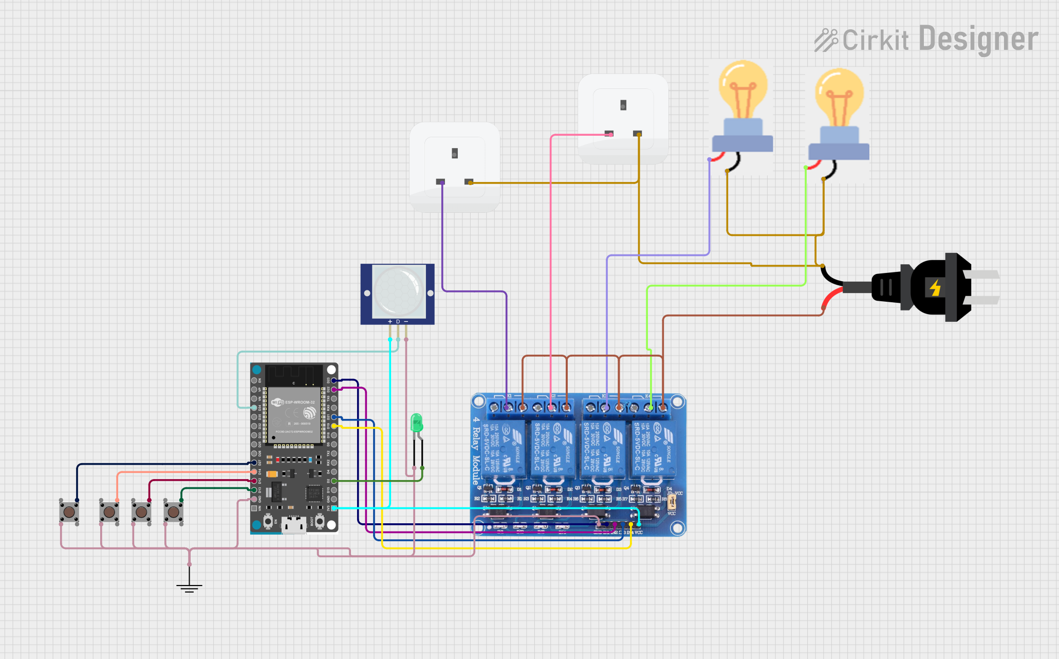
Circuit Documentation
Summary
The circuit in question is designed to control various devices, including relays, LEDs, and bulbs, using an ESP32 Devkit V1 microcontroller. The circuit includes pushbuttons for user input, a PIR motion sensor for detecting movement, and a 4-channel relay module for controlling AC-powered devices. The ESP32 Devkit V1 is the central processing unit that receives inputs from the pushbuttons and the PIR sensor to control the state of the LEDs and the relay channels, which in turn control the power to the bulbs and sockets.
Component List
ESP32 Devkit V1
- Microcontroller with WiFi and Bluetooth capabilities.
- It has multiple GPIO pins for interfacing with other components.
Relay 4 Channel 5v
- A module with 4 relays capable of controlling high voltage/current devices.
- Each relay has a Normally Open (NO) and a Normally Closed (NC) contact.
Pushbutton (4 instances)
- A simple pushbutton switch that provides a digital input to the microcontroller.
PIR Motion Sensor (Wokwi Compatible)
- A sensor that detects motion based on infrared signals.
- It provides a digital output signal.
LED: Two Pin (green)
- A basic green LED that lights up when powered.
Bulb (2 instances)
- Represents a generic light bulb that can be powered by an AC source.
AC source
- Provides alternating current power to the circuit.
Socket (2 instances)
- An AC power socket that can be controlled by the relay module.
GND
- A ground reference point for the circuit.
Wiring Details
ESP32 Devkit V1
3V3connected to Relay VCC and PIR Sensor VCC.D2connected to LED anode.D19,D21,D22,D23connected to Relay IN4, IN3, IN2, IN1 respectively.D34connected to PIR Sensor OUT.D27,D14,D12,D13connected to Pushbuttons.GNDconnected to common ground net.
Relay 4 Channel 5v
VCCconnected to ESP32 3V3.IN1,IN2,IN3,IN4connected to ESP32 D23, D22, D21, D19 respectively.COM1,COM2connected to Sockets life.COM3,COM4connected to Bulbs power.NO1,NO2,NO3,NO4connected to AC source +.GNDconnected to common ground net.
Pushbutton (4 instances)
Pin 3 (out)connected to ESP32 D27, D14, D12, D13 respectively.Pin 2 (in)connected to common ground net.
PIR Motion Sensor (Wokwi Compatible)
VCCconnected to ESP32 3V3.OUTconnected to ESP32 D34.GNDconnected to common ground net.
LED: Two Pin (green)
anodeconnected to ESP32 D2.cathodeconnected to common ground net.
Bulb (2 instances)
powerconnected to Relay COM3, COM4 respectively.GNDconnected to common ground net.
AC source
+connected to Relay NO1, NO2, NO3, NO4.-connected to common ground net.
Socket (2 instances)
lifeconnected to Relay COM1, COM2 respectively.neutralconnected to common ground net.
Documented Code
There is no code provided for the microcontroller. The expected behavior would be for the ESP32 to read inputs from the pushbuttons and the PIR sensor and control the state of the LED and relay channels accordingly. The code would likely involve setting up GPIO pins as inputs or outputs, reading digital inputs, and writing digital outputs to control the relays and LED. Without the actual code, we cannot provide further documentation on the software part of this circuit.