
Raspberry Pi Pico Controlled Smart Relay System with Emergency Stop
View and Edit Project In Cirkit Designer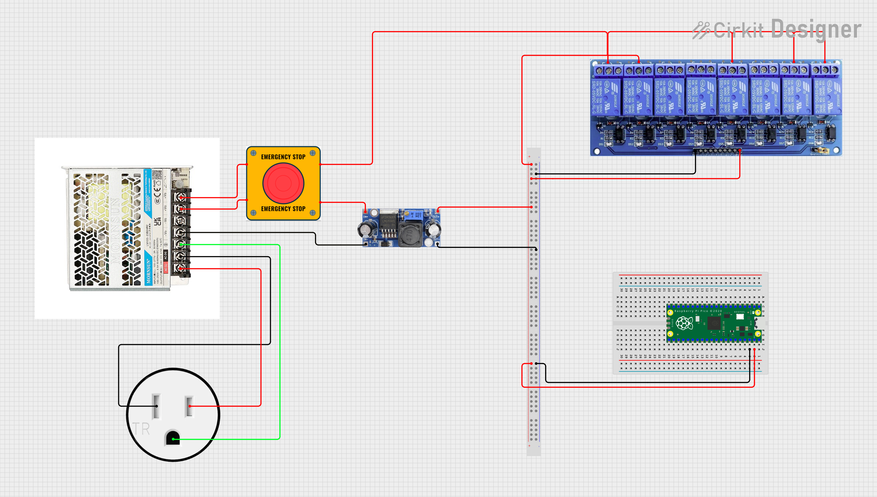
Circuit Documentation
Summary
This document provides a detailed overview of a circuit that includes a Raspberry Pi Pico microcontroller, a DC-DC converter, an AC-DC converter, an 8-channel relay module, an emergency stop button, and a 120V outlet. The circuit is designed to manage power conversion and control through the relay module, with the Raspberry Pi Pico serving as the central control unit.
Component List
BreadBoard
- Description: Standard breadboard for prototyping and connecting components.
- Pins: Multiple pins for various connections.
Convertisseur AC/DC LM100-23B12R2
- Description: AC to DC converter.
- Pins: AC (L), AC (N), Gnd, -V0, +V0
DC DC converter
- Description: DC to DC converter.
- Pins: +VCC IN, GND IN, +VCC OUT, GND OUT
120V Outlet
- Description: Standard 120V AC outlet.
- Pins: AC Neutral, AC Hot, GND
Raspberry Pi Pico
- Description: Microcontroller for controlling the circuit.
- Pins: pin 1 to pin 43
8 Channel Relay JD-VCC
- Description: Relay module for controlling high-power devices.
- Pins: JD-VCC, VCC, GND, In1 to In8, IN1_NC, IN1_COM, IN1_NO, IN2_NC, IN2_COM, IN2_NO, IN3_NC, IN3_COM, IN3_NO, IN4_NC, IN4_COM, IN4_NO, IN5_NC, IN5_COM, IN5_NO, IN6_NC, IN6_COM, IN6_NO, IN7_NC, IN7_COM, IN7_NO, IN8_NC, IN8_COM, IN8_NO
E Stop
- Description: Emergency stop button.
- Pins: NO 1, NO 2, NC 1, NC 2
Wiring Details
Raspberry Pi Pico
- pin 38 connected to BreadBoard pin19Y
- pin 39 connected to BreadBoard pin19Z
DC DC converter
- GND OUT connected to BreadBoard pin43Y
- +VCC OUT connected to BreadBoard pin52Z
- GND IN connected to Convertisseur AC/DC LM100-23B12R2 -V0
- +VCC IN connected to E Stop NC 2
Convertisseur AC/DC LM100-23B12R2
- AC (L) connected to 120V Outlet AC Hot
- AC (N) connected to 120V Outlet AC Neutral
- Gnd connected to 120V Outlet GND
- +V0 connected to E Stop NC 1
- +V0 connected to E Stop NO 1
8 Channel Relay JD-VCC
- VCC connected to BreadBoard pin58Z
- GND connected to BreadBoard pin59Y
- IN2_COM connected to BreadBoard pin61Z
- IN1_COM connected to E Stop NO 2
- IN5_COM connected to E Stop NO 2
- IN7_COM connected to E Stop NO 2
- IN8_COM connected to E Stop NO 2
120V Outlet
- AC Hot connected to Convertisseur AC/DC LM100-23B12R2 AC (L)
- AC Neutral connected to Convertisseur AC/DC LM100-23B12R2 AC (N)
- GND connected to Convertisseur AC/DC LM100-23B12R2 Gnd
E Stop
- NC 1 connected to Convertisseur AC/DC LM100-23B12R2 +V0
- NO 1 connected to Convertisseur AC/DC LM100-23B12R2 +V0
- NC 2 connected to DC DC converter +VCC IN
- NO 2 connected to 8 Channel Relay JD-VCC IN1_COM
- NO 2 connected to 8 Channel Relay JD-VCC IN5_COM
- NO 2 connected to 8 Channel Relay JD-VCC IN7_COM
- NO 2 connected to 8 Channel Relay JD-VCC IN8_COM
Code Documentation
Raspberry Pi Pico Code
sketch.ino
void setup() {
  // put your setup code here, to run once:

}

void loop() {
  // put your main code here, to run repeatedly:

}
documentation.txt
This document provides a comprehensive overview of the circuit, including a summary, component list, wiring details, and documented code for the Raspberry Pi Pico microcontroller.