555 Timer and 4017 Decade Counter Sequential LED Flasher
Circuit Documentation
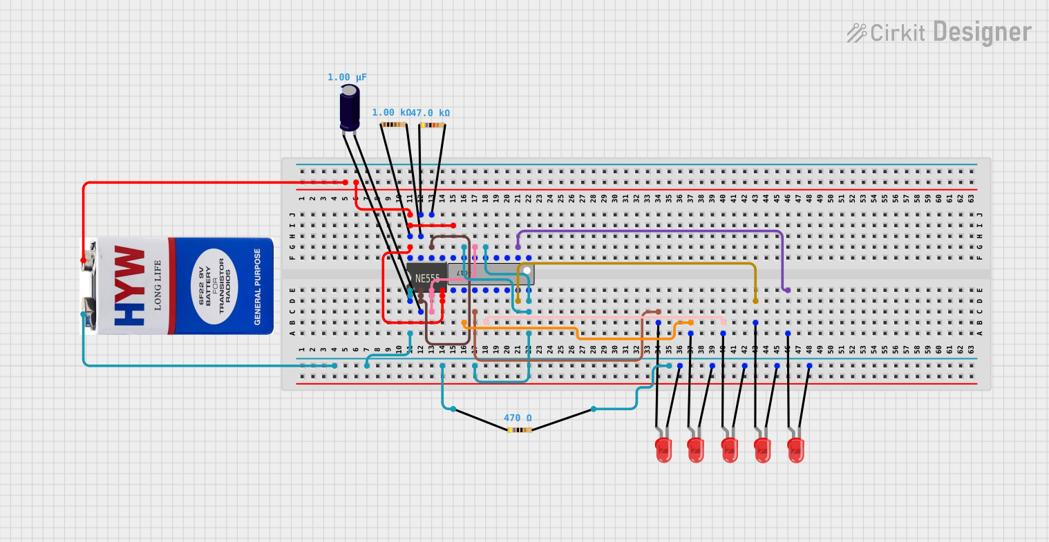
Summary
This circuit appears to be a sequential LED flasher using a 555 timer IC in conjunction with a 4017 decade counter IC. The 555 timer is likely configured in astable mode to generate clock pulses, which are then fed into the 4017 counter. The counter advances its output with each clock pulse, lighting up the connected LEDs in sequence. The circuit is powered by a 9V battery and includes resistors for current limiting and timing purposes, as well as an electrolytic capacitor for noise reduction or timing.
Component List
555 Timer IC
- Description: A highly stable device for generating accurate time delays or oscillation.
- Pins: VCC+, Dis, Th, CV, Rst, Out, Trig, GND
Resistor (1k Ohm)
- Description: A passive two-terminal electrical component that implements electrical resistance as a circuit element.
- Resistance: 1000 Ohms
Resistor (47k Ohm)
- Description: Another resistor providing higher resistance for timing or current limiting.
- Resistance: 47000 Ohms
4017 Decade Counter IC
- Description: A 5-stage divide-by-10 Johnson counter with 10 decoded outputs and a carry out bit.
- Pins: Q0-Q9 (Outputs 0-9), GND, VCC, MR (Reset), CLK (Clock), ~EN (Enable), ~CO (Carry Out)
Resistor (470 Ohm)
- Description: A resistor typically used for LED current limiting.
- Resistance: 470 Ohms
LED: Two Pin (red)
- Description: A red light-emitting diode used as a visual indicator.
- Pins: cathode, anode
Electrolytic Capacitor
- Description: A polarized capacitor with an anode (+) and cathode (-), used for filtering or timing applications.
- Capacitance: 1 microfarad (0.000001 Farads)
9V Battery
- Description: A standard 9-volt battery used as the power source for the circuit.
Wiring Details
555 Timer IC
- VCC+ connected to 9V battery positive terminal
- GND connected to the negative terminal of the electrolytic capacitor, cathodes of all LEDs, GND of 4017 IC, and negative terminal of the 9V battery
- Dis connected to 1k Ohm resistor and 47k Ohm resistor
- Th connected to the positive terminal of the electrolytic capacitor and 47k Ohm resistor
- Trig connected to the positive terminal of the electrolytic capacitor
- Out connected to Q7 (Output 7) of the 4017 IC
- Rst connected to the negative terminal of the 9V battery
Resistor (1k Ohm)
- One pin connected to VCC+ of the 555 Timer IC
- Other pin connected to Dis of the 555 Timer IC and one pin of the 47k Ohm resistor
Resistor (47k Ohm)
- One pin connected to Dis of the 555 Timer IC and one pin of the 1k Ohm resistor
- Other pin connected to Th of the 555 Timer IC
4017 Decade Counter IC
- VCC connected to the positive terminal of the 9V battery
- GND connected to the negative terminal of the 9V battery
- Q1 (Output 1) connected to the anode of an LED
- Q3 (Output 3) connected to the anode of an LED
- Q4 (Output 4) connected to the anode of an LED
- Q6 (Output 6) connected to the anode of an LED
- Q7 (Output 7) connected to Out of the 555 Timer IC
- Q9 (Output 9) connected to the anode of an LED
- ~CO (Carry Out) connected to the anode of an LED
- MR (Reset) connected to the anode of an LED
Resistor (470 Ohm)
- One pin connected to the positive terminal of the 9V battery
- Other pin connected to the anode of an LED
LED: Two Pin (red)
- Cathode connected to the negative terminal of the electrolytic capacitor, GND of the 555 Timer IC, and GND of the 4017 IC
- Anode connected to the respective outputs of the 4017 IC through individual 470 Ohm resistors
Electrolytic Capacitor
- Positive (+) terminal connected to Th and Trig of the 555 Timer IC
- Negative (-) terminal connected to GND of the 555 Timer IC and cathodes of all LEDs
9V Battery
- Positive (+) terminal connected to VCC+ of the 555 Timer IC and VCC of the 4017 IC
- Negative (-) terminal connected to GND of the 555 Timer IC and GND of the 4017 IC
Documented Code
There is no embedded code provided for this circuit as it does not contain any programmable microcontrollers. The operation of the circuit is purely hardware-based, relying on the timing characteristics of the 555 timer IC and the counting sequence of the 4017 decade counter IC.