
Arduino Uno R3-Based Environmental Monitoring System with Sound Detection and Data Logging
View and Edit Project In Cirkit Designer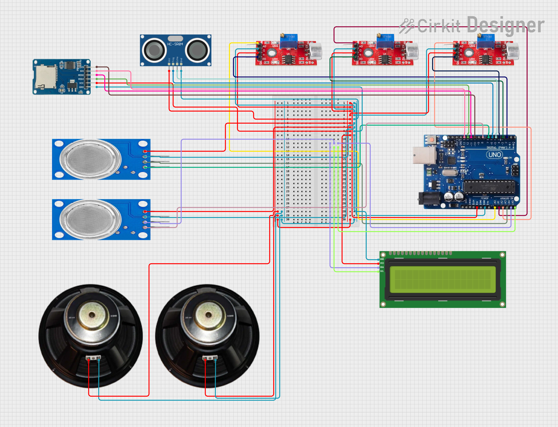
Circuit Documentation
Summary
This circuit integrates various sensors and modules with an Arduino Uno R3 microcontroller to perform multiple sensing and interactive tasks. The sensors include sound sensors, an HC-SR04 ultrasonic sensor, and MQ135 gas sensors. The circuit also features an I2C LCD 16x2 screen for display purposes and a Micro SD Card Module for data storage. The sound sensors detect noise levels, the ultrasonic sensor measures distance, and the MQ135 sensors monitor air quality. The Arduino Uno R3 serves as the central processing unit, interfacing with all the components to process the sensor data, control the display, and manage data logging.
Component List
Sound Sensor
- Pins: Analog, GND, VCC, Digital
- Description: Detects sound intensity levels and provides both analog and digital outputs.
HC-SR04 Ultrasonic Sensor
- Pins: VCC, TRIG, ECHO, GND
- Description: Measures distance by emitting ultrasonic waves and timing their return after reflecting off an object.
MQ135 Gas Sensor
- Pins: VCC, GND, A0, D0
- Description: Senses the concentration of gases in the air and provides both analog and digital outputs.
I2C LCD 16x2 Screen
- Pins: SCL, SDA, VCC (5V), GND, VDD, VO, RS, RW, E, D0-D7, BLA, BLK
- Description: Displays text and characters over two lines, each containing 16 characters.
Arduino Uno R3
- Pins: USB Port, Power Jack, IOREF, RESET, 3.3V, 5V, GND, VIN, Analog Inputs (A0-A5), Digital I/O (0-13), AREF
- Description: Microcontroller board based on the ATmega328P, with digital and analog I/O pins.
Speaker
- Pins: +, -
- Description: Outputs audio signals.
Micro SD Card Module
- Pins: cs, sck, mosi, miso, vcc, gnd
- Description: Enables reading from and writing to micro SD cards.
Wiring Details
Sound Sensor
- Analog: Connected to Arduino Uno Analog Pins (A0, A1, A2)
- GND: Connected to Arduino Uno GND
- VCC: Connected to Arduino Uno 5V
- Digital: Connected to Arduino Uno Digital Pins (2, 3, 4)
HC-SR04 Ultrasonic Sensor
- VCC: Connected to Arduino Uno 5V
- TRIG: Connected to Arduino Uno Digital Pin 6
- ECHO: Connected to Arduino Uno Digital Pin 5
- GND: Connected to Arduino Uno GND
MQ135 Gas Sensor
- VCC: Connected to Arduino Uno 5V
- GND: Connected to Arduino Uno GND
- A0: Connected to Arduino Uno Analog Pins (A3)
- D0: Connected to Arduino Uno Digital Pins (7, 8)
I2C LCD 16x2 Screen
- SCL: Connected to Arduino Uno A5/SCL
- SDA: Connected to Arduino Uno A4/SDA
- VCC (5V): Connected to Arduino Uno 5V
- GND: Connected to Arduino Uno GND
Speaker
- +: Connected to Arduino Uno 5V
- -: Connected to Arduino Uno GND
Micro SD Card Module
- cs: Connected to Arduino Uno Digital Pin 10
- sck: Connected to Arduino Uno Digital Pin 13
- mosi: Connected to Arduino Uno Digital Pin 11
- miso: Connected to Arduino Uno Digital Pin 12
- vcc: Connected to Arduino Uno 5V
- gnd: Connected to Arduino Uno GND
Documented Code
The provided code files are named sketch.ino and documentation.txt. However, the actual code content is not included in the input. The code would typically contain the setup and loop functions, initialization of the sensors and LCD, and logic for reading sensor data and displaying it or logging it to the SD card. Since the code content is missing, it cannot be documented here. Please provide the code content for detailed documentation.