
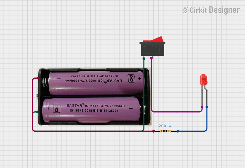
Circuit Documentation
Summary
This document provides a detailed description of a simple electrical circuit consisting of a rocker switch, a red LED, a resistor, and a 7.4V power source. The circuit is designed to control the LED using the rocker switch, with the resistor limiting the current to protect the LED.
Component List
Rocker Switch
- Pins: 1, 2
- Description: A switch used to control the flow of current in the circuit.
- Purpose: To turn the LED on and off.
LED: Two Pin (red)
- Pins: Cathode, Anode
- Description: A red light-emitting diode.
- Purpose: To emit light when current flows through it.
Resistor
- Pins: Pin1, Pin2
- Description: A resistor with a resistance of 200 Ohms.
- Purpose: To limit the current flowing through the LED to prevent damage.
7.4V Power Source
- Pins: +, -
- Description: A 7.4V DC power source.
- Purpose: To provide the necessary voltage for the circuit.
Wiring Details
Rocker Switch
- Pin 1 is connected to the + pin of the 7.4V power source.
- Pin 2 is connected to the cathode pin of the LED.
LED: Two Pin (red)
- Cathode is connected to Pin 2 of the rocker switch.
- Anode is connected to Pin 2 of the resistor.
Resistor
- Pin 1 is connected to the - pin of the 7.4V power source.
- Pin 2 is connected to the anode pin of the LED.
7.4V Power Source
- + pin is connected to Pin 1 of the rocker switch.
- - pin is connected to Pin 1 of the resistor.
Code
There is no microcontroller code associated with this circuit.
This documentation provides a comprehensive overview of the circuit, including a summary, detailed component descriptions, and wiring details. The circuit is designed to control an LED using a rocker switch, with a resistor to limit the current and a 7.4V power source to provide the necessary voltage.