
Arduino-Controlled Line Following Trolley with Ultrasonic Obstacle Detection and Bluetooth Connectivity
View and Edit Project In Cirkit Designer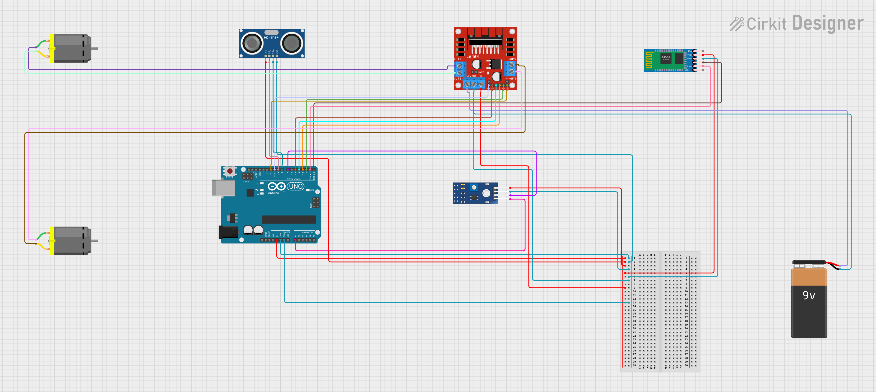
Circuit Documentation
Summary
This circuit is designed to control a line-following trolley using an array of sensors and modules. The core of the system is an Arduino UNO microcontroller, which interfaces with an HC-SR04 Ultrasonic Sensor for obstacle detection, an HC-05 Bluetooth Module for wireless communication, a TCRT 5000 IR Sensor for line tracking, and an L298N Motor Driver to control two DC motors. The circuit is powered by a 9V battery, and it includes logic for line following and obstacle avoidance.
Component List
HC-SR04 Ultrasonic Sensor
- Description: This sensor measures distance by emitting ultrasonic waves and measuring the time taken for the echo to return.
- Pins: VCC, TRIG, ECHO, GND
HC-05 Bluetooth Module
- Description: A wireless communication module that enables Bluetooth connectivity.
- Pins: Key, VCC, TXD, RXD, State, GND
DC Motor
- Description: An electric motor that converts electrical energy into mechanical rotation.
- Pins: pin 1, pin 2
9V Battery
- Description: A standard 9V battery providing the power source for the circuit.
- Pins: -, +
Arduino UNO
- Description: A microcontroller board based on the ATmega328P, used as the main controller for the trolley.
- Pins: UNUSED, IOREF, Reset, 3.3V, 5V, GND, Vin, A0-A5, SCL, SDA, AREF, D0-D13
L298N DC Motor Driver
- Description: A motor driver module that controls the direction and speed of DC motors.
- Pins: OUT1-OUT4, 12V, GND, 5V, 5V-ENA-JMP-I/O, +5V-J1/J2, ENA/B, IN1-IN4
TCRT 5000 IR SENSOR
- Description: An infrared sensor used for detecting the presence of a line or an object.
- Pins: VCC, GND, DO, AO
Wiring Details
HC-SR04 Ultrasonic Sensor
- VCC connected to Arduino 5V
- TRIG connected to Arduino D9
- ECHO connected to Arduino D8
- GND connected to Arduino GND
HC-05 Bluetooth Module
- VCC connected to Arduino 5V
- TXD connected to Arduino D0
- RXD connected to Arduino D1
- GND connected to Arduino GND
DC Motors
- Motor 1 pin 1 connected to L298N OUT1
- Motor 1 pin 2 connected to L298N OUT2
- Motor 2 pin 1 connected to L298N OUT3
- Motor 2 pin 2 connected to L298N OUT4
9V Battery
-
- connected to L298N 12V
-
- connected to L298N GND
L298N DC Motor Driver
- 5V connected to Arduino 5V
- GND connected to Arduino GND
- OUT1-OUT4 connected to DC Motors
- ENA connected to Arduino D10
- ENB connected to Arduino D11
- IN1 connected to Arduino D5
- IN2 connected to Arduino D4
- IN3 connected to Arduino D3
- IN4 connected to Arduino D2
TCRT 5000 IR SENSOR
- VCC connected to Arduino 5V
- GND connected to Arduino GND
- DO connected to Arduino D7
- AO connected to Arduino A0
Documented Code
/*
 * Arduino Sketch for a Line Following Trolley
 *
 * This code interfaces with various sensors and modules to control a trolley
 * that follows a line. The components include an HC-SR04 Ultrasonic Sensor,
 * HC-05 Bluetooth Module, TCRT 5000 IR Sensor, and L298N Motor Driver.
 * The Arduino UNO is the main microcontroller.
 */

// Pin definitions
const int trigPin = 9;
const int echoPin = 8;
const int irPin = A0;
const int irDigitalPin = 7;
const int motorIn1 = 5;
const int motorIn2 = 4;
const int motorIn3 = 3;
const int motorIn4 = 2;
const int motorEnA = 10;
const int motorEnB = 11;

void setup() {
  // Initialize serial communication
  Serial.begin(9600);

  // Initialize pins
  pinMode(trigPin, OUTPUT);
  pinMode(echoPin, INPUT);
  pinMode(irPin, INPUT);
  pinMode(irDigitalPin, INPUT);
  pinMode(motorIn1, OUTPUT);
  pinMode(motorIn2, OUTPUT);
  pinMode(motorIn3, OUTPUT);
  pinMode(motorIn4, OUTPUT);
  pinMode(motorEnA, OUTPUT);
  pinMode(motorEnB, OUTPUT);
}

void loop() {
  // Read IR sensor
  int irValue = analogRead(irPin);
  int irDigitalValue = digitalRead(irDigitalPin);

  // Line following logic
  if (irDigitalValue == HIGH) {
    // Move forward
    digitalWrite(motorIn1, HIGH);
    digitalWrite(motorIn2, LOW);
    digitalWrite(motorIn3, HIGH);
    digitalWrite(motorIn4, LOW);
    analogWrite(motorEnA, 255);
    analogWrite(motorEnB, 255);
  } else {
    // Stop
    digitalWrite(motorIn1, LOW);
    digitalWrite(motorIn2, LOW);
    digitalWrite(motorIn3, LOW);
    digitalWrite(motorIn4, LOW);
    analogWrite(motorEnA, 0);
    analogWrite(motorEnB, 0);
  }

  // Ultrasonic sensor logic
  long duration, distance;
  digitalWrite(trigPin, LOW);
  delayMicroseconds(2);
  digitalWrite(trigPin, HIGH);
  delayMicroseconds(10);
  digitalWrite(trigPin, LOW);
  duration = pulseIn(echoPin, HIGH);
  distance = (duration / 2) / 29.1;

  // If an obstacle is detected within 10 cm, stop the motors
  if (distance < 10) {
    digitalWrite(motorIn1, LOW);
    digitalWrite(motorIn2, LOW);
    digitalWrite(motorIn3, LOW);
    digitalWrite(motorIn4, LOW);
    analogWrite(motorEnA, 0);
    analogWrite(motorEnB, 0);
  }

  delay(100);
}
This code is responsible for the operation of the line-following trolley. It initializes the sensor and motor driver pins, reads the IR sensor for line tracking, and uses the ultrasonic sensor to detect obstacles. The motors are controlled based on the sensor inputs to follow a line and avoid collisions.