
Arduino UNO-Based Motion Detection System with I2C LCD Display and Buzzer Alert
View and Edit Project In Cirkit Designer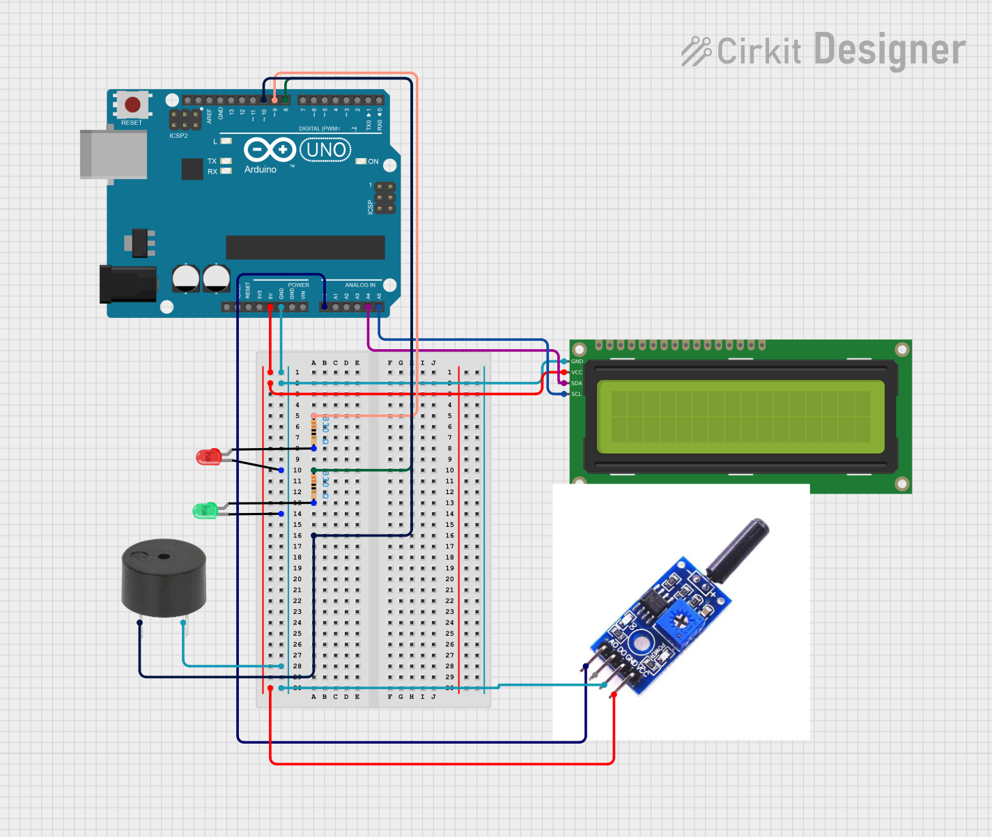
Circuit Documentation
Summary
This circuit involves an Arduino UNO microcontroller interfacing with various components including a 16x2 I2C LCD, a red LED, a green LED, a buzzer, and a vibration sensor (sw-18010p). The circuit is designed to display warnings on the LCD and activate the buzzer and LEDs based on the input from the vibration sensor.
Component List
Arduino UNO
- Description: A microcontroller board based on the ATmega328P.
- Pins: UNUSED, IOREF, Reset, 3.3V, 5V, GND, Vin, A0, A1, A2, A3, A4, A5, SCL, SDA, AREF, D13, D12, D11, D10, D9, D8, D7, D6, D5, D4, D3, D2, D1, D0
16x2 I2C LCD
- Description: A 16x2 character LCD display with I2C interface.
- Pins: GND, VCC, SDA, SCL
sw-18010p
- Description: A vibration sensor.
- Pins: None
Resistor (330 Ohms)
- Description: A resistor with a resistance of 330 Ohms.
- Pins: pin1, pin2
LED: Two Pin (red)
- Description: A red LED.
- Pins: cathode, anode
Resistor (330 Ohms)
- Description: A resistor with a resistance of 330 Ohms.
- Pins: pin1, pin2
buzzer
- Description: A buzzer.
- Pins: PIN, GND
LED: Two Pin (green)
- Description: A green LED.
- Pins: cathode, anode
Wiring Details
Arduino UNO
- 5V connected to VCC of 16x2 I2C LCD and sw-18010p.
- GND connected to GND of 16x2 I2C LCD, cathode of red LED, cathode of green LED, GND of buzzer, and sw-18010p.
- D9 connected to pin1 of a 330 Ohm resistor.
- D8 connected to pin1 of another 330 Ohm resistor.
- D10 connected to PIN of the buzzer.
- A0 connected to sw-18010p.
- A4 connected to SDA of 16x2 I2C LCD.
- A5 connected to SCL of 16x2 I2C LCD.
16x2 I2C LCD
- VCC connected to 5V of Arduino UNO.
- GND connected to GND of Arduino UNO.
- SDA connected to A4 of Arduino UNO.
- SCL connected to A5 of Arduino UNO.
sw-18010p
- Connected to 5V and GND of Arduino UNO.
- Connected to A0 of Arduino UNO.
Resistor (330 Ohms)
- pin1 connected to D9 of Arduino UNO.
- pin2 connected to anode of red LED.
Resistor (330 Ohms)
- pin1 connected to D8 of Arduino UNO.
- pin2 connected to anode of green LED.
LED: Two Pin (red)
- cathode connected to GND of Arduino UNO.
- anode connected to pin2 of a 330 Ohm resistor.
LED: Two Pin (green)
- cathode connected to GND of Arduino UNO.
- anode connected to pin2 of another 330 Ohm resistor.
buzzer
- PIN connected to D10 of Arduino UNO.
- GND connected to GND of Arduino UNO.
Code Documentation
int led = 8 ;
int led1 = 9 ;
int buzzer = 10 ;

// LCD를 사용하기 위해 헤더파일을 추가합니다
#include <LiquidCrystal_I2C.h>
#include <Wire.h>
LiquidCrystal_I2C lcd(0x27, 16, 2); // 16x2 LCD객체를 생성합니다. 이때 확인한 I2C의 주소값을 넣어줍니다

void setup()
{
    pinMode(8,OUTPUT) ; //8번핀에 출력함
    pinMode(9,OUTPUT) ; //9번핀에 출력함
    pinMode(10, OUTPUT) ; //10번핀에 출력함

     lcd.init();
     lcd.backlight();
}

void loop()
{
    int dec = analogRead(A0);
    if ( dec < 800 )
    {
       Serial.println(dec);
       tone(buzzer, 1000) ;
       digitalWrite(9,HIGH);
       digitalWrite(8,LOW);
        delay(100);
        lcd.setCursor(0,0); // 0번 행 0번 열부터 출력합니다
        lcd.print("    WARNING    "); // WARNING을 표시함
        delay(1000);
        lcd.clear();
    }
    else
    {
         Serial.println(dec);
        noTone(buzzer) ;
         digitalWrite(8,HIGH);
         digitalWrite(9,LOW);
        delay(100);
    }
}
This code initializes the pins for the LEDs and the buzzer, sets up the LCD, and continuously reads the analog input from the vibration sensor. If the sensor value is below a threshold, it activates the buzzer and the red LED, and displays a warning on the LCD. If the sensor value is above the threshold, it deactivates the buzzer and activates the green LED.