
Circuit Documentation
Summary
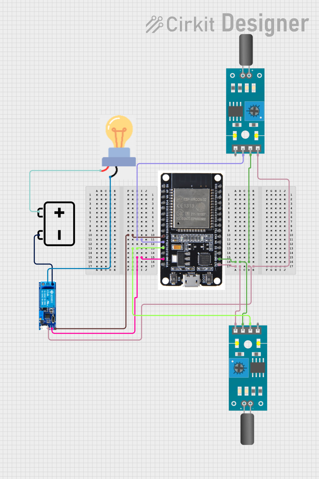
This circuit is designed to control a bulb using a relay module, which is triggered by an ESP32 microcontroller. The ESP32 receives input from two tilt sensors. The circuit is powered by a 12V battery.
Component List
Bulb
- Description: A standard bulb.
- Pins: GND, power
Tilt Sensor (1)
- Description: A sensor that detects tilt.
- Pins: A0, D0, GND, VCC
Tilt Sensor (2)
- Description: A sensor that detects tilt.
- Pins: A0, D0, GND, VCC
Relay Module 5V-30V
- Description: A relay module that can switch high voltage devices.
- Pins: common contact, normally open, normally closed, trigger, V-, V+
12V Battery
- Description: A 12V power source.
- Pins: -, +
ESP32
- Description: A microcontroller with Wi-Fi and Bluetooth capabilities.
- Pins: EN, VP, VN, D34, D35, D32, D33, D25, D26, D27, D14, D12, D13, GND, VIN, 3V3, D15, D2, D4, RX2, TX2, D5, D18, D19, D21, RX0, TX0, D22, D23, BOOT
Wiring Details
Bulb
- GND is connected to the common contact of the Relay Module 5V-30V.
- power is connected to the + terminal of the 12V Battery.
Tilt Sensor (1)
- D0 is connected to D14 of the ESP32.
- GND is connected to GND of the ESP32.
- VCC is connected to 3V3 of the ESP32.
Tilt Sensor (2)
- D0 is connected to D12 of the ESP32.
- GND is connected to GND of the ESP32.
- VCC is connected to 3V3 of the ESP32.
Relay Module 5V-30V
- trigger is connected to D27 of the ESP32.
- V- is connected to GND of the ESP32.
- V+ is connected to 3V3 of the ESP32.
- normally open is connected to the - terminal of the 12V Battery.
12V Battery
- - is connected to the normally open pin of the Relay Module 5V-30V.
- + is connected to the power pin of the Bulb.
ESP32
- D27 is connected to the trigger pin of the Relay Module 5V-30V.
- D14 is connected to the D0 pin of Tilt Sensor (1).
- D12 is connected to the D0 pin of Tilt Sensor (2).
- GND is connected to the GND pins of both Tilt Sensors and the V- pin of the Relay Module 5V-30V.
- 3V3 is connected to the VCC pins of both Tilt Sensors and the V+ pin of the Relay Module 5V-30V.
Code
No code is provided for this circuit.