
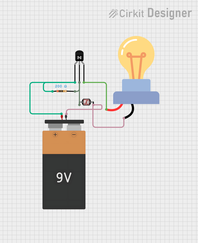
Circuit Documentation
Summary of the Circuit
The circuit described by the provided inputs appears to be a simple light-sensitive switch using a photocell (LDR) to control the state of an LED bulb. When the light level falling on the photocell changes, it alters the current flowing through the base of an NPN transistor, which in turn controls the current through the LED bulb. A resistor is included to limit the current through the transistor's base. The circuit is powered by a 9V battery.
Component List
NPN Transistor (EBC)
- Description: A standard NPN bipolar junction transistor with three pins: emitter, base, and collector.
- Purpose: Acts as a switch or amplifier in the circuit, controlling the LED bulb based on the photocell's resistance.
Resistor
- Description: A passive two-terminal electrical component that implements electrical resistance as a circuit element.
- Value: 200 Ohms
- Purpose: Limits the current flowing into the base of the NPN transistor to protect it from damage.
Photocell (LDR)
- Description: A light-dependent resistor whose resistance changes based on the ambient light level.
- Purpose: Senses the ambient light level to control the state of the NPN transistor and, consequently, the LED bulb.
LED bulb AC / Bombillo AC
- Description: A light-emitting diode designed to operate with AC voltage.
- Purpose: Serves as the output indicator of the circuit, lighting up when the transistor is in the conducting state.
Battery 9V
- Description: A standard 9V battery with two terminals: VCC and GND.
- Purpose: Provides the necessary power to the circuit.
Wiring Details
NPN Transistor (EBC)
- Emitter: Connected to the VCC of the 9V battery.
- Base: Connected to pin 2 of the Resistor and pin 0 of the Photocell (LDR).
- Collector: Connected to the "+" pin of the LED bulb AC.
Resistor
- Pin 1: Connected to the VCC of the 9V battery.
- Pin 2: Connected to the base of the NPN Transistor and pin 0 of the Photocell (LDR).
Photocell (LDR)
- Pin 0: Connected to pin 2 of the Resistor and the base of the NPN Transistor.
- Pin 1: Connected to the GND of the 9V battery and the "-" pin of the LED bulb AC.
LED bulb AC / Bombillo AC
- +: Connected to the collector of the NPN Transistor.
- -: Connected to the GND of the 9V battery and pin 1 of the Photocell (LDR).
Battery 9V
- VCC: Connected to the emitter of the NPN Transistor and pin 1 of the Resistor.
- GND: Connected to pin 1 of the Photocell (LDR) and the "-" pin of the LED bulb AC.
Documented Code
There is no embedded code provided for any microcontrollers in this circuit. Therefore, this section is not applicable to the current documentation.