
Arduino-Controlled Dual DC Motor System with IR and Gas Sensing
View and Edit Project In Cirkit Designer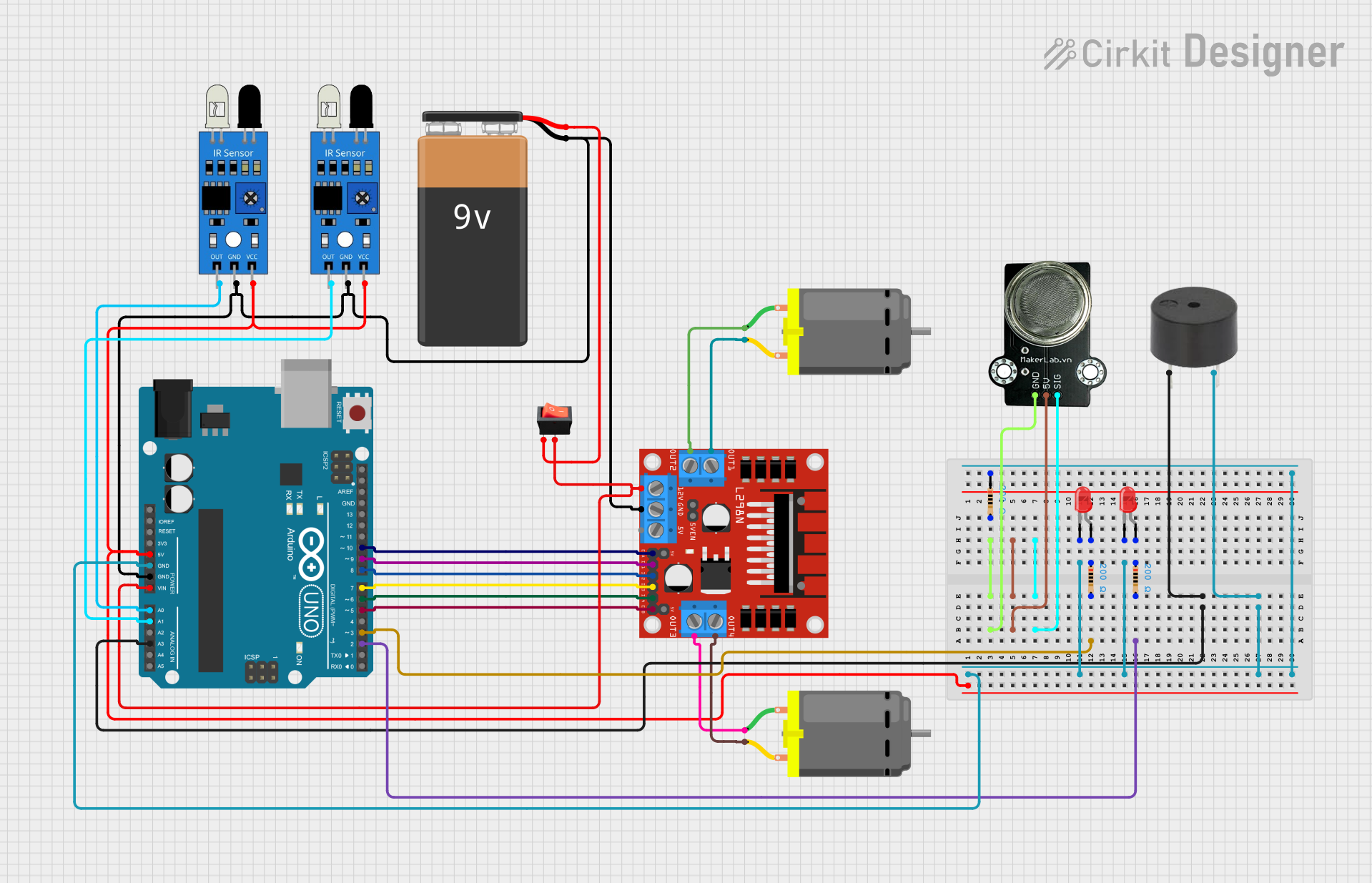
Circuit Documentation
Summary
This circuit is designed to control two DC motors using an L298N DC motor driver, interfaced with an Arduino UNO microcontroller. The circuit includes sensors (IR and MQ-2 gas sensor), actuators (DC motors, buzzer, and LEDs), and a power supply (9V battery). The Arduino UNO is responsible for processing sensor inputs and controlling the actuators based on the programmed logic. The circuit also features a rocker switch to control power flow and resistors to limit current to the LEDs.
Component List
Microcontrollers
- Arduino UNO: A microcontroller board based on the ATmega328P, with a variety of digital and analog I/O pins.
Sensors
- IR Sensor: Used to detect obstacles or measure distances.
- MKE-S08 MQ-2 Sensor: A gas sensor used for detecting levels of combustible gases in the air.
Actuators
- L298N DC Motor Driver: An integrated circuit that allows for controlling the speed and direction of two DC motors.
- DC Motor: Converts electrical energy into mechanical motion.
- Buzzer: An electronic device that produces sound.
- LED (Red): A light-emitting diode that emits red light.
Power Supply
- 9V Battery: Provides the power required for the circuit.
Switches
- Rocker Switch: A switch to control the connection of the battery to the circuit.
Passive Components
- Resistor: A component that limits the flow of electric current, used here to protect the LEDs.
Wiring Details
Arduino UNO
- GND: Connected to the ground plane of the circuit.
- 5V: Powers the IR sensors.
- Vin: Receives power from the L298N motor driver 12V output through the rocker switch.
- A0, A1: Connected to the output of the IR sensors.
- A3: Connected to the buzzer.
- D2, D3: Connected to resistors leading to LEDs.
- D5, D6, D7, D8, D9, D10: Control signals for the L298N motor driver.
L298N DC Motor Driver
- OUT1, OUT2: Connected to one DC motor.
- OUT3, OUT4: Connected to another DC motor.
- 12V: Receives power from the 9V battery through the rocker switch.
- GND: Connected to the ground plane of the circuit.
- ENA, ENB: Enable pins for the motor outputs, controlled by the Arduino.
- IN1, IN2, IN3, IN4: Input pins for controlling motor direction, connected to the Arduino.
DC Motors
- Pin 1, Pin 2: Connected to the output pins of the L298N motor driver.
IR Sensors
- VCC: Powered by the 5V output from the Arduino.
- GND: Connected to the ground plane of the circuit.
- Out: Signal pins connected to the Arduino analog inputs.
Buzzer
- PIN: Connected to the Arduino A3 pin.
- GND: Connected to the ground plane of the circuit.
LEDs
- Anode: Connected to the Arduino through a resistor.
- Cathode: Connected to the ground plane of the circuit.
Resistors
- Pin1: Connected to the anode of the LEDs.
- Pin2: Connected to the Arduino digital pins D2 and D3.
Rocker Switch
- Input: Connected to the positive terminal of the 9V battery.
- Output: Connected to the 12V input of the L298N motor driver and Vin of the Arduino.
9V Battery
- +: Connected to the input of the rocker switch.
- -: Connected to the ground plane of the circuit.
Documented Code
Arduino UNO Code
void setup() {
  // put your setup code here, to run once:

}

void loop() {
  // put your main code here, to run repeatedly:

}
L298N DC Motor Driver Code
void setup() {
  // put your setup code here, to run once:

}

void loop() {
  // put your main code here, to run repeatedly:

}
Note: The actual logic for controlling the motors and reading the sensors is not included in the provided code snippets and should be implemented according to the specific requirements of the application.