
Arduino Mega 2560-Based Smart Soil Monitoring System with Bluetooth Connectivity
View and Edit Project In Cirkit Designer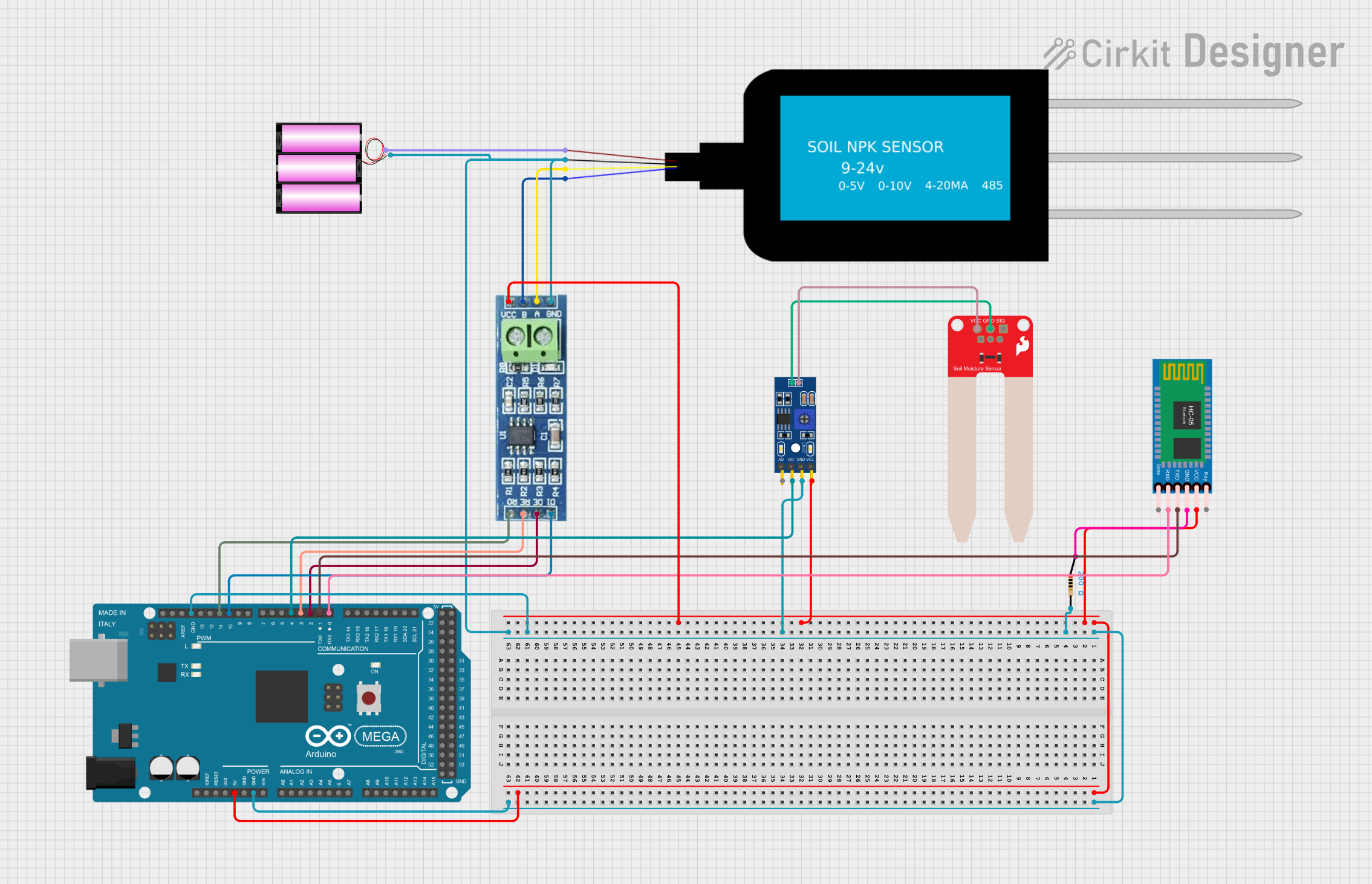
Circuit Documentation
Summary
This document provides a detailed overview of a circuit that includes an Arduino Mega 2560 microcontroller, various sensors, a Bluetooth module, and an RS485 communication module. The circuit is designed to interface with soil sensors and communicate data wirelessly via Bluetooth and RS485.
Component List
Arduino Mega 2560
- Description: A microcontroller board based on the ATmega2560.
- Pins: IOREF, RESET, 3V3, 5V, GND, VIN, A0-A15, D0-D53, AREF, SDA, SCL
NPK Soil Sensor
- Description: A sensor used to measure the nitrogen, phosphorus, and potassium levels in soil.
- Pins: VCC, GND, A, B
LM393
- Description: A voltage comparator.
- Pins: A0, D0, GND, VCC
RS485
- Description: A communication module for RS485 protocol.
- Pins: VCC, RO, RE, GND, B, A, DE, DI
SparkFun Soil Moisture Sensor
- Description: A sensor used to measure soil moisture levels.
- Pins: VCC, GND, SIG
HC-05 Bluetooth Module
- Description: A Bluetooth module for wireless communication.
- Pins: Key, VCC, TXD, RXD, State, GND
Resistor
- Description: A 200 Ohm resistor.
- Pins: pin1, pin2
Battery 12V
- Description: A 12V battery for power supply.
- Pins: +, -
Wiring Details
Arduino Mega 2560
5V is connected to:
- VCC of HC-05 Bluetooth Module
- VCC of LM393
- VCC of RS485
GND is connected to:
- pin2 of Resistor
- GND of LM393
- GND of RS485
- GND of NPK Soil Sensor
- GND of SparkFun Soil Moisture Sensor
D0 RX0 is connected to RXD of HC-05 Bluetooth Module
D1 TX0 is connected to TXD of HC-05 Bluetooth Module
D2 PWM is connected to DE of RS485
D3 PWM is connected to RE of RS485
D4 PWM is connected to D0 of LM393
D10 PWM is connected to DI of RS485
D11 PWM is connected to RO of RS485
NPK Soil Sensor
- VCC is connected to + of Battery 12V
- GND is connected to GND of Arduino Mega 2560
- A is connected to A of RS485
- B is connected to B of RS485
LM393
- VCC is connected to 5V of Arduino Mega 2560
- GND is connected to GND of Arduino Mega 2560
- D0 is connected to D4 PWM of Arduino Mega 2560
RS485
- VCC is connected to 5V of Arduino Mega 2560
- GND is connected to GND of Arduino Mega 2560
- DE is connected to D2 PWM of Arduino Mega 2560
- RE is connected to D3 PWM of Arduino Mega 2560
- DI is connected to D10 PWM of Arduino Mega 2560
- RO is connected to D11 PWM of Arduino Mega 2560
- A is connected to A of NPK Soil Sensor
- B is connected to B of NPK Soil Sensor
SparkFun Soil Moisture Sensor
- VCC is connected to VCC of LM393
- GND is connected to GND of LM393
HC-05 Bluetooth Module
- VCC is connected to 5V of Arduino Mega 2560
- GND is connected to pin1 of Resistor
- RXD is connected to D0 RX0 of Arduino Mega 2560
- TXD is connected to D1 TX0 of Arduino Mega 2560
Resistor
- pin1 is connected to GND of HC-05 Bluetooth Module
- pin2 is connected to GND of Arduino Mega 2560
Battery 12V
- + is connected to VCC of NPK Soil Sensor
- - is connected to GND of Arduino Mega 2560
Documented Code
Arduino Mega 2560 Code
void setup() {
  // put your setup code here, to run once:

}

void loop() {
  // put your main code here, to run repeatedly:

}
This code initializes the Arduino Mega 2560 and contains empty setup and loop functions, which can be filled with the necessary logic to interface with the connected sensors and modules.