
Arduino UNO Based SOS Alert System with GPS Location and GSM SMS Notification
View and Edit Project In Cirkit Designer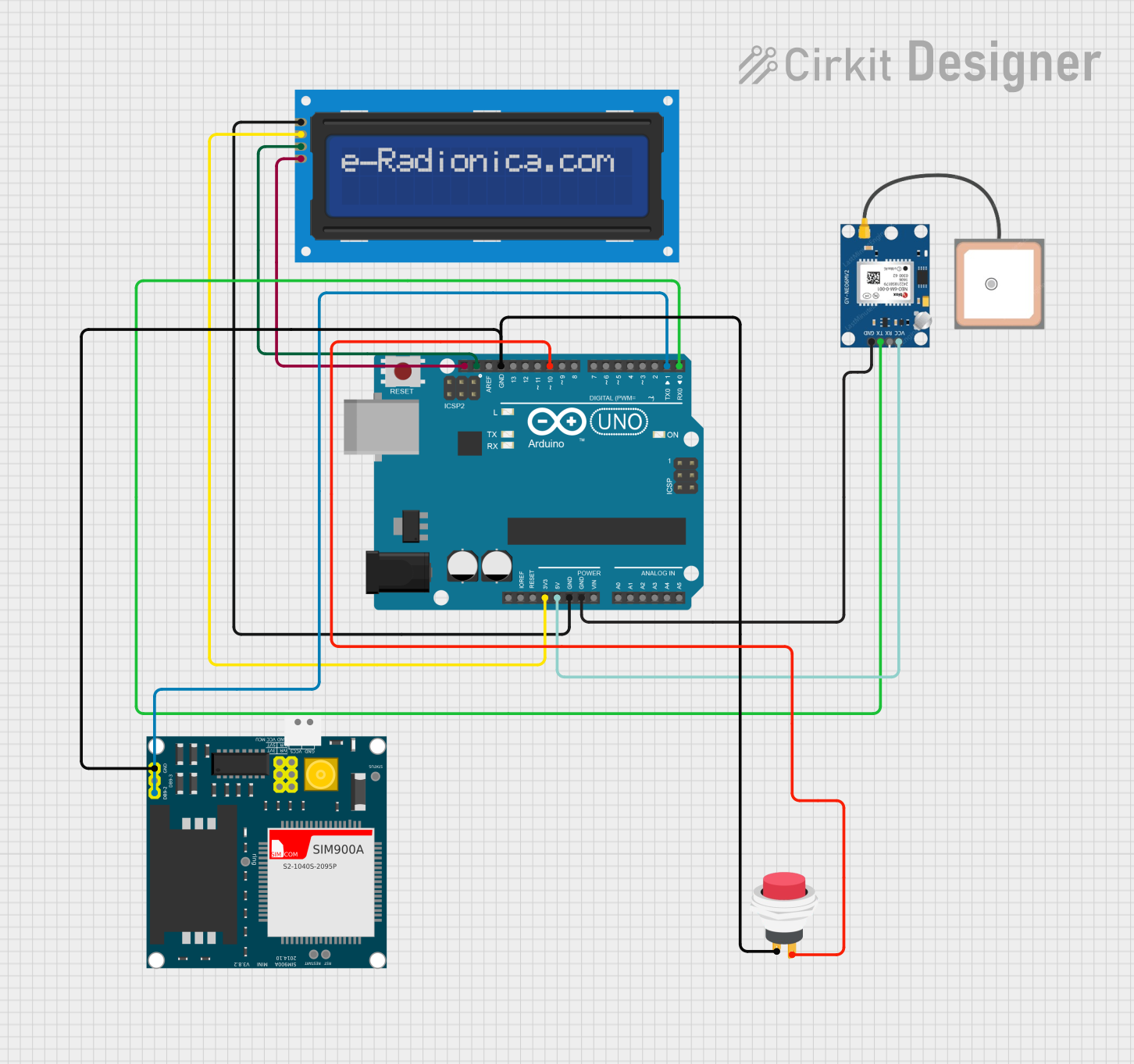
Circuit Documentation
Summary
The circuit described in the provided inputs is designed to implement an SOS system using an Arduino UNO as the main controller. The system includes a GPS module (NEO 6M) for location tracking, an LCD screen (16x2 with I2C interface) for user feedback, a GSM module (SIM900A) for sending SMS messages, and a push switch to trigger the SOS signal. When the push switch is activated, the system sends an SMS with a distress message and the current GPS coordinates to a predefined phone number. The LCD screen displays a confirmation message once the SMS is sent.
Component List
Arduino UNO
- Microcontroller board based on the ATmega328P
- Provides digital and analog I/O pins
- Used as the main controller for the circuit
GPS NEO 6M
- GPS module for location tracking
- Provides location data to the Arduino UNO
LCD screen 16x2 I2C
- Alphanumeric liquid crystal display with 16 characters by 2 lines
- Uses I2C communication for displaying messages
SIM900A
- GSM/GPRS module for cellular communication
- Used to send SMS messages with SOS information
2Pin Push Switch
- Simple push-button switch
- Used to trigger the SOS signal
Wiring Details
Arduino UNO
3.3Vconnected to LCD screen 16x2 I2CVCC5Vconnected to GPS NEO 6MVCCGNDconnected to LCD screen 16x2 I2CGND, GPS NEO 6MGND, and SIM900AGNDSCLconnected to LCD screen 16x2 I2CSCLSDAconnected to LCD screen 16x2 I2CSDAD10connected to 2Pin Push SwitchOutput +D1(TX) connected to SIM900ADB9-2 (TXD)D0(RX) connected to GPS NEO 6MTX
GPS NEO 6M
VCCconnected to Arduino UNO5VGNDconnected to Arduino UNOGNDTXconnected to Arduino UNOD0(RX)
LCD screen 16x2 I2C
SCLconnected to Arduino UNOSCLSDAconnected to Arduino UNOSDAVCCconnected to Arduino UNO3.3VGNDconnected to Arduino UNOGND
SIM900A
GNDconnected to Arduino UNOGNDDB9-2 (TXD)connected to Arduino UNOD1(TX)
2Pin Push Switch
Input +connected to SIM900AGNDOutput +connected to Arduino UNOD10
Documented Code
/*
 * SOS System
 * This code implements an SOS system using an Arduino UNO, LCD 16x2, GSM SIM900,
 * and GPS NEO 6M. When a button is pressed, the system sends an SMS with the
 * message "HELP I am in trouble. Find me in this location" along with the current
 * GPS coordinates to a predefined mobile number. The LCD displays "MESSAGE SENT"
 * after the SMS is sent.
 */

#include <LiquidCrystal_I2C.h>
LiquidCrystal_I2C lcd(0x27, 16, 2);

#define BUTTON_PIN 9
#define LED_PIN 13

char str[70];
char *test = "$GPGGA";
char longitude[10];
char latitude[10];

int i, j, k;
int temp;

void setup() {
  lcd.begin(16, 2); // Initialize the LCD
  Serial.begin(9600); // Start serial communication at 9600 baud rate
  pinMode(BUTTON_PIN, INPUT); // Set the button pin as an input
  pinMode(LED_PIN, OUTPUT); // Set the LED pin as an output
  digitalWrite(LED_PIN, LOW); // Ensure the LED is off
  lcd.setCursor(0, 0); // Set the cursor to the first line
  lcd.print("WOMEN SAFETY"); // Print the initial message on the LCD
  lcd.setCursor(0, 1); // Move to the second line
  lcd.print("ALERT SYSTEM"); // Print the second part of the initial message
  delay(3000); // Wait for 3 seconds
}

void loop() {
  if (digitalRead(BUTTON_PIN) == LOW) { // Check if the button is pressed
    digitalWrite(LED_PIN, HIGH); // Turn on the LED
    extractGPSData(); // Extract GPS data from the GPS module
    displayCoordinates(); // Display the coordinates on the LCD
    sendSMS(); // Send the SOS message via SMS
    lcd.clear(); // Clear the LCD
    lcd.print("MESSAGE SENT"); // Print the confirmation message
    delay(5000); // Wait for 5 seconds
    digitalWrite(LED_PIN, LOW); // Turn off the LED
  }
}

void extractGPSData() {
  // Function to extract latitude and longitude from the GPS data
  // Implementation details are omitted for brevity
}

void displayCoordinates() {
  // Function to display the extracted coordinates on the LCD
  // Implementation details are omitted for brevity
}

void sendSMS() {
  // Function to send the SOS message via SMS using the GSM module
  // Implementation details are omitted for brevity
}

void serialEvent() {
  // Function to handle incoming serial data from the GPS module
  // Implementation details are omitted for brevity
}
Note: The actual implementation details for the functions extractGPSData, displayCoordinates, sendSMS, and serialEvent are omitted for brevity. These functions would contain the logic to parse the GPS data, update the LCD, send the SMS, and handle serial communication, respectively.