Cirkit Designer
Your all-in-one circuit design IDE
Home /
Project Documentation
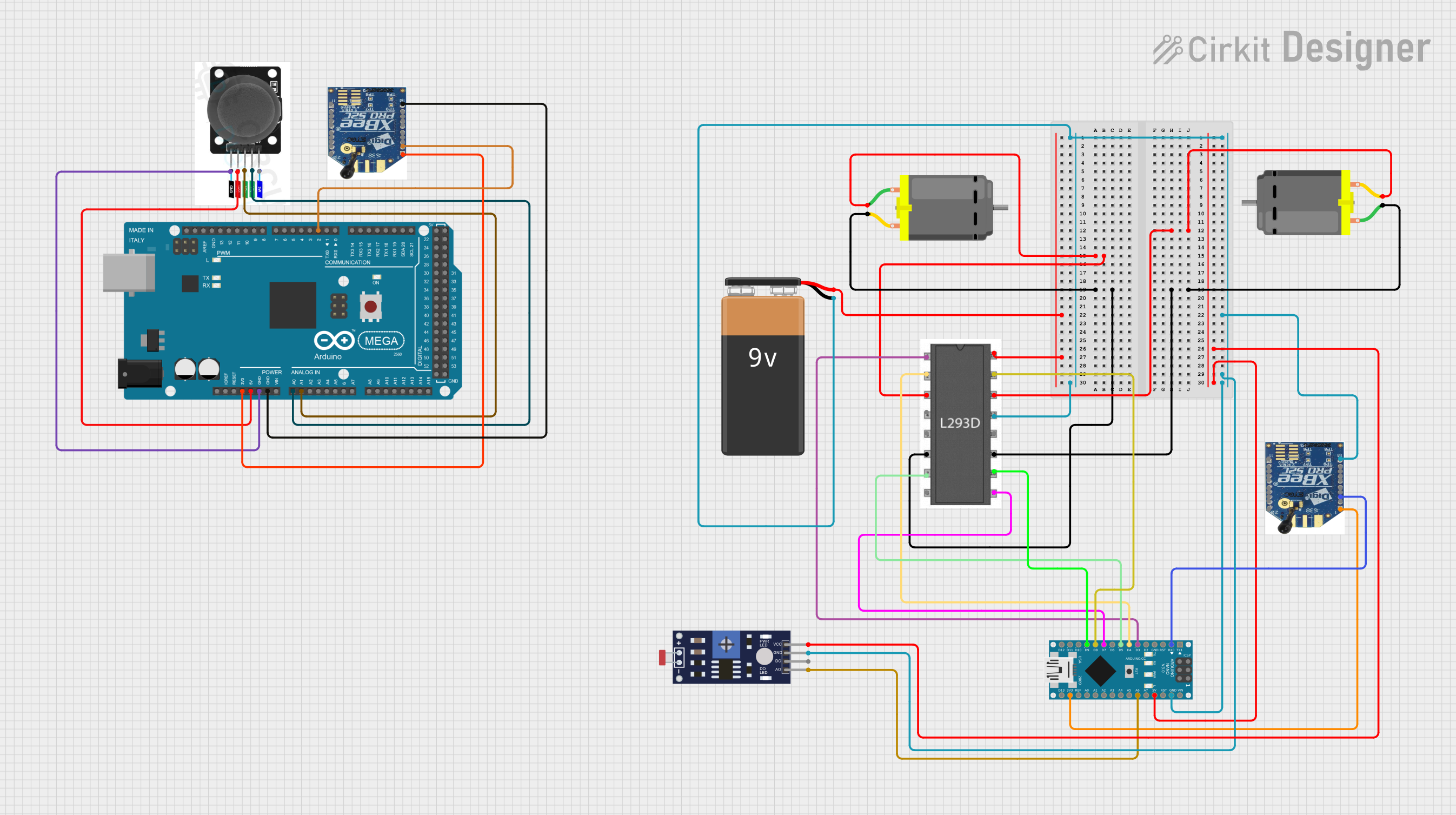
Arduino and XBEE Controlled Dual DC Motor System with Joystick and Photoresistor
Circuit Documentation
Summary
This document provides a detailed overview of a circuit that includes various components such as DC motors, an XBEE module, an L293D motor driver, an Arduino Nano, a photoresistor sensor, a joystick module, an Arduino Mega 2560, and a 9V battery. The circuit is designed to control DC motors using the Arduino Nano and Mega, with additional functionalities provided by the XBEE module and sensors.
Component List
DC Motor
- Description: A motor that converts electrical energy into mechanical energy.
- Pins: pin 1, pin 2
XBEE s2c
- Description: A wireless communication module.
- Pins: Vcc, DOUT, DIN/CONFIG, DIO12, RESET, PWM, DIO 11, RESERVED, DTR, GND, AD0, AD1, AD2, AD3, RTS, ASC, VREF, ON/SLEEP, CTS/DIO7, DIO4
L293D
- Description: A motor driver IC used to control the direction and speed of DC motors.
- Pins: Enable 1,2, Input 1, Output 1, GND, Output 2, Input 2, Vcc2, Vcc1, Input 4, Output 4, Output 3, Input 3, Enable 3,4
Arduino Nano
- Description: A small, complete, and breadboard-friendly microcontroller board.
- Pins: D1/TX, D0/RX, RESET, GND, D2, D3, D4, D5, D6, D7, D8, D9, D10, D11/MOSI, D12/MISO, VIN, 5V, A7, A6, A5, A4, A3, A2, A1, A0, AREF, 3V3, D13/SCK
Photoresistor (LDR) Sensor (Wokwi Compatible)
- Description: A light-dependent resistor used to detect light levels.
- Pins: VCC, GND, DO, AO
Joystick Module
- Description: A module used to detect directional input.
- Pins: SW, VRY, VRX, VCC, GND
Arduino Mega 2560
- Description: A microcontroller board based on the ATmega2560.
- Pins: IOREF, RESET, 3V3, 5V, GND, VIN, A0, A1, A2, A3, A4, A5, A6, A7, A8, A9, A10, A11, A12, A13, A14, A15, D21/SCL, D20/SDA, D19/RX1, D18/TX1, D17 PWM/RX2, D16 PWM/TX2, D15/RX3, D14/TX3, D0 RX0, D1 TX0, D2 PWM, D3 PWM, D4 PWM, D5 PWM, D6 PWM, D7 PWM, D8 PWM, D9 PWM, D10 PWM, D11 PWM, D12 PWM, D13 PWM, AREF, SDA, SCL, D52, D50, D48, D46, D44, D42, D40, D38, D36, D34, D32, D30, D28, D26, D24, D22, D53, D51, D49, D47, D45, D43, D41, D39, D37, D35, D33, D31, D29, D27, D25, D23
9V Battery
- Description: A power source for the circuit.
- Pins: -, +
Wiring Details
DC Motor 1
- pin 1 connected to L293D Output 3
- pin 2 connected to L293D Output 4
DC Motor 2
- pin 1 connected to L293D Output 1
- pin 2 connected to L293D Output 2
XBEE s2c (Instance 1)
- Vcc connected to Arduino Nano 3V3
- GND connected to 9V Battery -
- DIN/CONFIG connected to Arduino Nano D0/RX
XBEE s2c (Instance 2)
- Vcc connected to Arduino Mega 2560 3V3
- GND connected to Arduino Mega 2560 GND
- DOUT connected to Arduino Mega 2560 D2 PWM
L293D
- GND connected to 9V Battery -
- Vcc1 connected to 9V Battery +
- Enable 1,2 connected to Arduino Nano D3
- Input 1 connected to Arduino Nano D4
- Input 2 connected to Arduino Nano D5
- Input 3 connected to Arduino Nano D9
- Input 4 connected to Arduino Nano D8
- Enable 3,4 connected to Arduino Nano D7
Arduino Nano
- GND connected to 9V Battery -
- 5V connected to Photoresistor Sensor VCC
- A6 connected to Photoresistor Sensor AO
Photoresistor (LDR) Sensor
- GND connected to 9V Battery -
- VCC connected to Arduino Nano 5V
- AO connected to Arduino Nano A6
Joystick Module
- VRY connected to Arduino Mega 2560 A0
- VRX connected to Arduino Mega 2560 A1
- VCC connected to Arduino Mega 2560 5V
- GND connected to Arduino Mega 2560 GND
9V Battery
- - connected to XBEE s2c GND, Photoresistor Sensor GND, L293D GND, Arduino Nano GND
- + connected to L293D Vcc1
Documented Code
Arduino Nano Code
void setup() {
  // put your setup code here, to run once:

}

void loop() {
  // put your main code here, to run repeatedly:

}
Arduino Mega 2560 Code
void setup() {
  // put your setup code here, to run once:

}

void loop() {
  // put your main code here, to run repeatedly:

}
This document provides a comprehensive overview of the circuit, including the components used, their connections, and the code running on the microcontrollers.