
Arduino UNO Bluetooth-Controlled Robotic Arm with Servo Motors and DC Motors
View and Edit Project In Cirkit Designer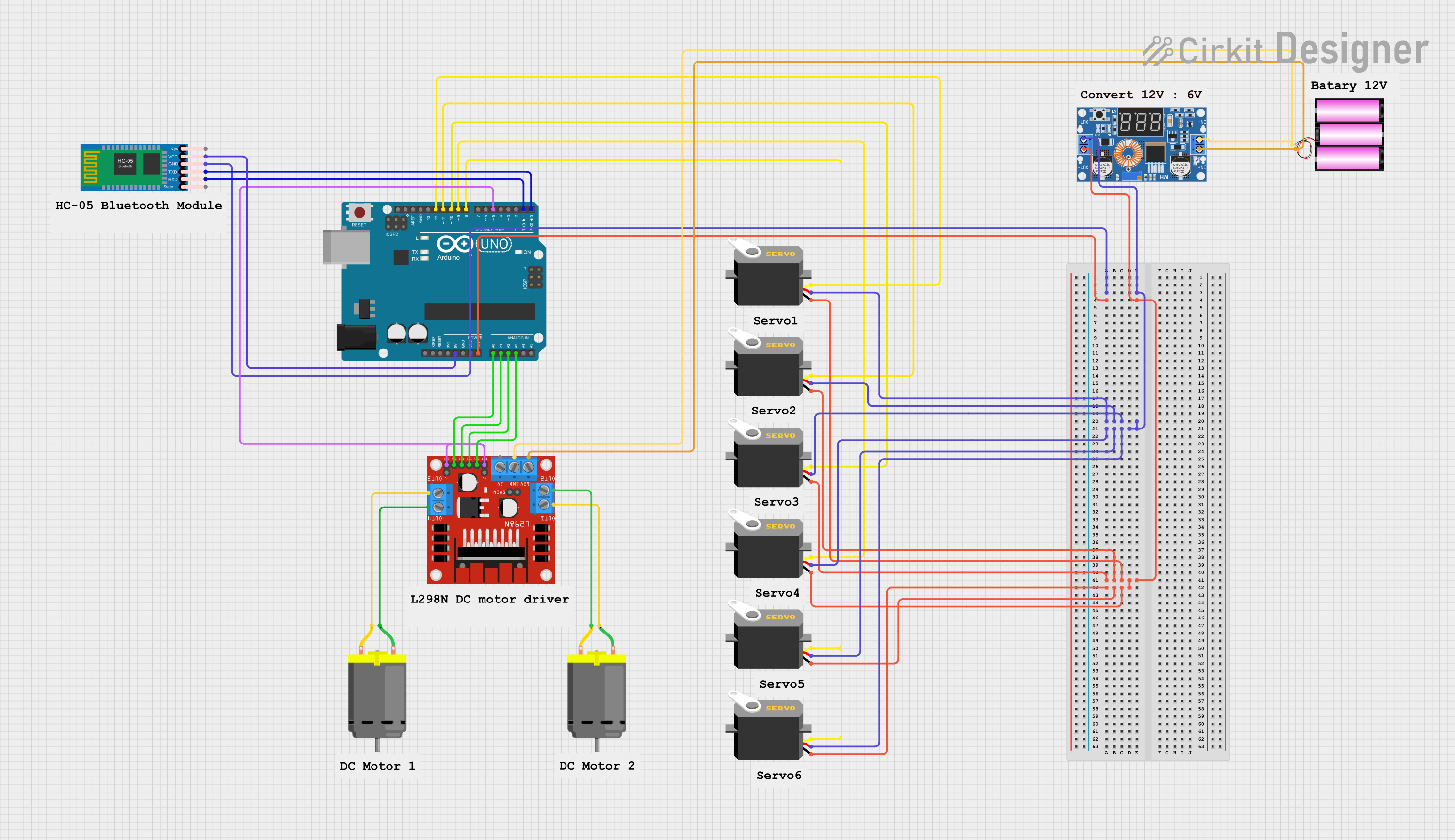
Circuit Documentation
Summary
This circuit is designed to control multiple servos and DC motors using an Arduino UNO microcontroller. It includes a Bluetooth module for wireless communication, a DC motor driver for controlling the motors, and a DC buck step-down converter for power regulation. The circuit is powered by a 12V battery.
Component List
Arduino UNO
- Description: Microcontroller board based on the ATmega328P.
- Pins: UNUSED, IOREF, Reset, 3.3V, 5V, GND, Vin, A0, A1, A2, A3, A4, A5, SCL, SDA, AREF, D13, D12, D11, D10, D9, D8, D7, D6, D5, D4, D3, D2, D1, D0
XL4015 5A DC Buck Step-down
- Description: DC-DC buck converter for voltage regulation.
- Pins: Output +, Output -, Input +, Input -
HC-05 Bluetooth Module
- Description: Bluetooth module for wireless communication.
- Pins: Key, VCC, GND, TXD, RXD, State
L298N DC Motor Driver
- Description: Dual H-Bridge motor driver for controlling DC motors.
- Pins: OUT1, OUT2, 12V, GND, 5V, OUT3, OUT4, 5V-ENA-JMP-I, 5V-ENA-JMP-O, +5V-J1, +5V-J2, ENA, IN1, IN2, IN3, IN4, ENB
Servo
- Description: Servo motor for precise control of angular position.
- Pins: gnd, vcc, pulse
Battery 12V
- Description: 12V battery for powering the circuit.
- Pins: +, -
DC Motor
- Description: DC motor for rotational motion.
- Pins: pin 1, pin 2
Wiring Details
Arduino UNO
- 5V connected to VCC of HC-05 Bluetooth Module
- GND connected to vcc of multiple Servos and GND of HC-05 Bluetooth Module
- Vin connected to gnd of multiple Servos and Output + of XL4015 5A DC Buck Step-down
- A0 connected to IN4 of L298N DC Motor Driver
- A1 connected to IN3 of L298N DC Motor Driver
- A2 connected to IN2 of L298N DC Motor Driver
- A3 connected to IN1 of L298N DC Motor Driver
- D12 connected to pulse of a Servo
- D11 connected to pulse of a Servo
- D10 connected to pulse of a Servo
- D9 connected to pulse of a Servo
- D8 connected to pulse of multiple Servos
- D5 connected to ENA and ENB of L298N DC Motor Driver
- D1 connected to RXD of HC-05 Bluetooth Module
- D0 connected to TXD of HC-05 Bluetooth Module
XL4015 5A DC Buck Step-down
- Output - connected to vcc of multiple Servos and GND of Arduino UNO
- Output + connected to gnd of multiple Servos and Vin of Arduino UNO
- Input + connected to 12V of L298N DC Motor Driver and + of Battery 12V
- Input - connected to GND of L298N DC Motor Driver and - of Battery 12V
HC-05 Bluetooth Module
- VCC connected to 5V of Arduino UNO
- GND connected to GND of Arduino UNO
- TXD connected to D0 of Arduino UNO
- RXD connected to D1 of Arduino UNO
L298N DC Motor Driver
- IN4 connected to A0 of Arduino UNO
- IN3 connected to A1 of Arduino UNO
- IN2 connected to A2 of Arduino UNO
- IN1 connected to A3 of Arduino UNO
- ENA connected to D5 of Arduino UNO
- ENB connected to D5 of Arduino UNO
- 12V connected to Input + of XL4015 5A DC Buck Step-down and + of Battery 12V
- GND connected to Input - of XL4015 5A DC Buck Step-down and - of Battery 12V
- OUT1 connected to pin 1 of a DC Motor
- OUT2 connected to pin 2 of a DC Motor
- OUT3 connected to pin 2 of a DC Motor
- OUT4 connected to pin 1 of a DC Motor
Servo
- vcc connected to GND of Arduino UNO and Output - of XL4015 5A DC Buck Step-down
- gnd connected to Vin of Arduino UNO and Output + of XL4015 5A DC Buck Step-down
- pulse connected to various digital pins (D8, D9, D10, D11, D12) of Arduino UNO
Battery 12V
- + connected to Input + of XL4015 5A DC Buck Step-down and 12V of L298N DC Motor Driver
- - connected to Input - of XL4015 5A DC Buck Step-down and GND of L298N DC Motor Driver
DC Motor
- pin 1 connected to OUT1 of L298N DC Motor Driver
- pin 2 connected to OUT2 of L298N DC Motor Driver
- pin 1 connected to OUT4 of L298N DC Motor Driver
- pin 2 connected to OUT3 of L298N DC Motor Driver
Documented Code
Arduino UNO Code
#include <Servo.h>

Servo motor_1;
Servo motor_2;
Servo motor_3;
Servo motor_4;
Servo motor_5;

#define enA 5  //Enable1 L298 Pin enA
#define in1 A3 //Motor1  L298 Pin in1
#define in2 A2 //Motor1  L298 Pin in1
#define in3 A1 //Motor2  L298 Pin in1
#define in4 A0 //Motor2  L298 Pin in1
#define enB 5  //Enable2 L298 Pin enB

int servo1 = 90;
int servo2 = 110;
int servo3 = 40;
int servo4 = 50;
int servo5 = 90;

int bt_data;
int Speed = 255;

void setup(){

  Serial.begin(9600); // initialize serial communication at 9600 bits per second:

  motor_1.attach(8);
  motor_2.attach(9);
  motor_3.attach(10);
  motor_4.attach(11);
  motor_5.attach(12);

  motor_1.write(servo1);
  motor_2.write(servo2);
  motor_3.write(servo3);
  motor_4.write(servo4);
  motor_5.write(servo5);

  pinMode(enA, OUTPUT); // declare as output for L298 Pin enA
  pinMode(in1, OUTPUT); // declare as output for L298 Pin in1
  pinMode(in2, OUTPUT); // declare as output for L298 Pin in2
  pinMode(in3, OUTPUT); // declare as output for L298 Pin in3
  pinMode(in4, OUTPUT); // declare as output for L298 Pin in4
  pinMode(enB, OUTPUT); // declare as output for L298 Pin enB

  delay(1000);
}

void loop(){
  //if some date is sent, reads it and saves in state

  if(Serial.available() > 0){
    bt_data = Serial.read();
    Serial.println(bt_data);
    if(bt_data > 20){Speed = bt_data;}
  }

  analogWrite(enA, Speed); // Write The Duty Cycle 0 to 255 Enable Pin A for Motor1 Speed
  analogWrite(enB, Speed); // Write The Duty Cycle 0 to 255 Enable Pin B for Motor2 Speed

  if(bt_data == 1){forword(); }  // if the bt_data is '1' the DC motor will go forward
  else if(bt_data == 2){backword();}  // if the bt_data is '2' the motor will Reverse
  else if(bt_data == 3){turnLeft();}