
Wi-Fi Controlled Robotic System with ESP32-CAM and Brushless Motor
View and Edit Project In Cirkit Designer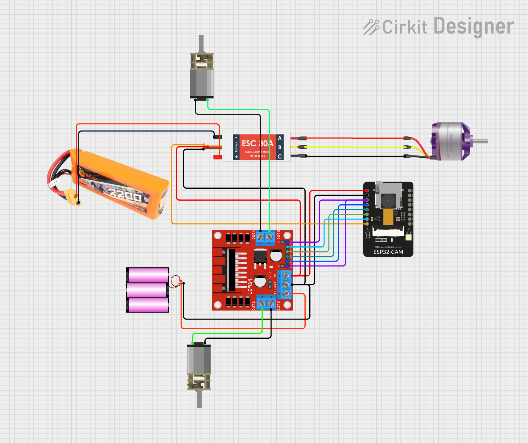
Circuit Documentation
Summary
This document provides a detailed overview of a circuit that includes a LiPo battery, an Electronic Speed Controller (ESC), an ESP32-CAM, an L298N DC motor driver, a 12V battery, a brushless motor, and two DC mini metal gear motors. The circuit is designed to control the brushless motor and the DC motors using the ESP32-CAM microcontroller.
Component List
LiPo Battery 2200mAH 30C
- Description: A rechargeable lithium polymer battery with a capacity of 2200mAh and a discharge rate of 30C.
- Pins: VCC, GND
Electronic Speed Controller (ESC)
- Description: A device used to control the speed of an electric motor.
- Pins: Battery VCC, Battery GND, Signal, 5V out, GND out, M1, M2, M3
ESP32-CAM
- Description: A low-cost microcontroller with integrated Wi-Fi and Bluetooth, featuring a camera module.
- Pins: 5V, GND, IO12, IO13, IO15, IO14, IO2, IO4, VOT, VOR, VCC, IO0, IO16, 3V3
L298N DC Motor Driver
- Description: A dual H-Bridge motor driver that allows control of two DC motors.
- Pins: OUT1, OUT2, 12V, GND, 5V, OUT3, OUT4, 5V-ENA-JMP-I, 5V-ENA-JMP-O, +5V-J1, +5V-J2, ENA, IN1, IN2, IN3, IN4, ENB
12V Battery
- Description: A 12V battery used to power the L298N motor driver.
- Pins: +, -
Brushless Motor
- Description: A type of electric motor that is powered by an ESC.
- Pins: L1, L2, L3
DC Mini Metal Gear Motor
- Description: A small DC motor with metal gears for increased torque.
- Pins: IN1, IN2
Wiring Details
LiPo Battery 2200mAH 30C
- VCC is connected to Battery VCC of the Electronic Speed Controller (ESC).
- GND is connected to Battery GND of the Electronic Speed Controller (ESC).
Electronic Speed Controller (ESC)
- Battery VCC is connected to VCC of the LiPo Battery.
- Battery GND is connected to GND of the LiPo Battery.
- Signal is connected to IO4 of the ESP32-CAM.
- 5V out is connected to 5V of the ESP32-CAM and 5V of the L298N DC Motor Driver.
- GND out is connected to - of the 12V Battery, GND of the ESP32-CAM, and GND of the L298N DC Motor Driver.
- M1 is connected to L1 of the Brushless Motor.
- M2 is connected to L2 of the Brushless Motor.
- M3 is connected to L3 of the Brushless Motor.
ESP32-CAM
- 5V is connected to 5V out of the Electronic Speed Controller (ESC).
- GND is connected to GND out of the Electronic Speed Controller (ESC).
- IO4 is connected to Signal of the Electronic Speed Controller (ESC).
- IO12 is connected to ENA and ENB of the L298N DC Motor Driver.
- IO13 is connected to IN1 of the L298N DC Motor Driver.
- IO15 is connected to IN2 of the L298N DC Motor Driver.
- IO14 is connected to IN3 of the L298N DC Motor Driver.
- IO2 is connected to IN4 of the L298N DC Motor Driver.
L298N DC Motor Driver
- 5V is connected to 5V out of the Electronic Speed Controller (ESC).
- GND is connected to GND out of the Electronic Speed Controller (ESC).
- 12V is connected to + of the 12V Battery.
- OUT1 is connected to IN2 of the first DC Mini Metal Gear Motor.
- OUT2 is connected to IN1 of the first DC Mini Metal Gear Motor.
- OUT3 is connected to IN2 of the second DC Mini Metal Gear Motor.
- OUT4 is connected to IN1 of the second DC Mini Metal Gear Motor.
- ENA and ENB are connected to IO12 of the ESP32-CAM.
- IN1 is connected to IO13 of the ESP32-CAM.
- IN2 is connected to IO15 of the ESP32-CAM.
- IN3 is connected to IO14 of the ESP32-CAM.
- IN4 is connected to IO2 of the ESP32-CAM.
12V Battery
- + is connected to 12V of the L298N DC Motor Driver.
- - is connected to GND out of the Electronic Speed Controller (ESC).
Brushless Motor
- L1 is connected to M1 of the Electronic Speed Controller (ESC).
- L2 is connected to M2 of the Electronic Speed Controller (ESC).
- L3 is connected to M3 of the Electronic Speed Controller (ESC).
DC Mini Metal Gear Motor (First)
- IN1 is connected to OUT2 of the L298N DC Motor Driver.
- IN2 is connected to OUT1 of the L298N DC Motor Driver.
DC Mini Metal Gear Motor (Second)
- IN1 is connected to OUT4 of the L298N DC Motor Driver.
- IN2 is connected to OUT3 of the L298N DC Motor Driver.
Code
No code is provided for this circuit.