
Arduino Nano-Based Remote-Controlled Dual Motor System with LiPo Battery
View and Edit Project In Cirkit Designer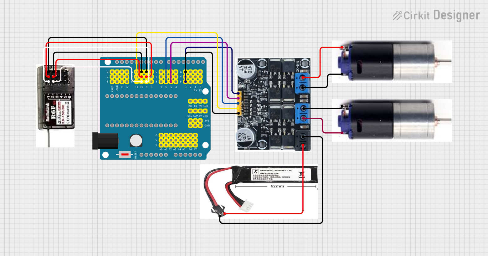
Circuit Documentation
Summary
This document provides a detailed overview of a circuit that includes a NANO Shield Board, a ZK-BM1 10A Motor Driver, an 11.1V LiPo battery, an R6FG Receiver, and two GM25 DC Motors. The circuit is designed to control the motors using the motor driver, with inputs from the receiver and the NANO Shield Board.
Component List
NANO Shield Board W/ Power Switch
- Description: A versatile microcontroller board with multiple I/O pins.
- Pins: A0, A1, A2, A3, A4/SDA, A5/SCL, A6, A7, VCC, GND, 3V3, D0/RX, D1/TX, D2, D3 PWM, D4, D5 PWM, D6 PWM, D7, D8, D9 PWM, D10 PWM/SS, D11 PWM/MOSI, D12/MISO, D13/SCK, AREF, RST, NC, VIN
ZK-BM1 10A Motor Driver
- Description: A motor driver capable of handling up to 10A of current.
- Pins: B+, B-, M1A, M1B, M2A, M2B, IN1, IN2, IN3, IN4, GND
11.1V LiPo Battery
- Description: A rechargeable lithium polymer battery providing 11.1V.
- Pins: +VE, GND
R6FG Receiver
- Description: A receiver module for remote control signals.
- Pins: GND, VCC, CH1, CH2
GM25 DC Motor
- Description: A DC motor used for driving mechanical components.
- Pins: +VE, -VE
Wiring Details
NANO Shield Board W/ Power Switch
- D3 PWM is connected to IN1 of the ZK-BM1 10A Motor Driver.
- GND is connected to GND of the ZK-BM1 10A Motor Driver.
- D5 PWM is connected to IN2 of the ZK-BM1 10A Motor Driver.
- D6 PWM is connected to IN3 of the ZK-BM1 10A Motor Driver.
- D9 PWM is connected to CH1 of the R6FG Receiver.
- VCC is connected to VCC of the R6FG Receiver.
- GND is connected to GND of the R6FG Receiver.
- D10 PWM/SS is connected to CH2 of the R6FG Receiver.
- D11 PWM/MOSI is connected to IN4 of the ZK-BM1 10A Motor Driver.
ZK-BM1 10A Motor Driver
- IN1 is connected to D3 PWM of the NANO Shield Board.
- GND is connected to GND of the NANO Shield Board.
- IN2 is connected to D5 PWM of the NANO Shield Board.
- IN3 is connected to D6 PWM of the NANO Shield Board.
- IN4 is connected to D11 PWM/MOSI of the NANO Shield Board.
- B+ is connected to +VE of the 11.1V LiPo Battery.
- B- is connected to GND of the 11.1V LiPo Battery.
- M1A is connected to -VE of the first GM25 DC Motor.
- M1B is connected to +VE of the first GM25 DC Motor.
- M2A is connected to -VE of the second GM25 DC Motor.
- M2B is connected to +VE of the second GM25 DC Motor.
11.1V LiPo Battery
- +VE is connected to B+ of the ZK-BM1 10A Motor Driver.
- GND is connected to B- of the ZK-BM1 10A Motor Driver.
R6FG Receiver
- CH1 is connected to D9 PWM of the NANO Shield Board.
- VCC is connected to VCC of the NANO Shield Board.
- GND is connected to GND of the NANO Shield Board.
- CH2 is connected to D10 PWM/SS of the NANO Shield Board.
GM25 DC Motor (First)
- -VE is connected to M1A of the ZK-BM1 10A Motor Driver.
- +VE is connected to M1B of the ZK-BM1 10A Motor Driver.
GM25 DC Motor (Second)
- -VE is connected to M2A of the ZK-BM1 10A Motor Driver.
- +VE is connected to M2B of the ZK-BM1 10A Motor Driver.
Code
No code is provided for this circuit.