
Raspberry Pi 4B and MMWave Radar Sensor-Based Smart LED Indicator
View and Edit Project In Cirkit Designer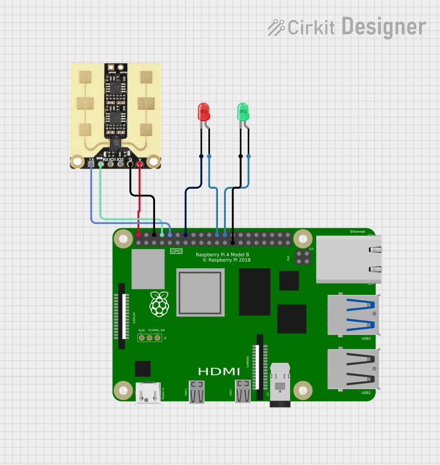
Circuit Documentation
Summary
This document provides a detailed overview of a circuit that integrates a Raspberry Pi 4B, an MMWave radar sensor, and two LEDs (one red and one green). The Raspberry Pi 4B serves as the central control unit, interfacing with the radar sensor and controlling the LEDs.
Component List
Raspberry Pi 4B
- Description: A powerful single-board computer with multiple GPIO pins for interfacing with various peripherals.
- Pins: 3V3, 5V, GPIO2, GPIO3, GND, GPIO4, GPIO14, GPIO15, GPIO17, GPIO18, GPIO27, GPIO22, GPIO23, GPIO24, GPIO10, GPIO9, GPIO25, GPIO11, GPIO8, GPIO7, ID_SD, GPIO5, GPIO6, GPIO12, GPIO13, GPIO19, GPIO16, GPIO26, GPIO20, GPIO21, ID_SC, TR01_TAP, TR00_TAP, TR03_TAP, TR02_TAP, RUN, GLOBAL_EN
MMWave Radar Sensor
- Description: A sensor module used for motion detection and range measurement using millimeter-wave technology.
- Pins: TX, RX, IO1, IO2, GND, VGG
LED: Two Pin (red)
- Description: A red LED with two pins: anode and cathode.
- Pins: cathode, anode
LED: Two Pin (green)
- Description: A green LED with two pins: anode and cathode.
- Pins: cathode, anode
Wiring Details
Raspberry Pi 4B
- 5V is connected to VGG of the MMWave radar sensor.
- GND is connected to:
- GND of the MMWave radar sensor.
- cathode of the red LED.
- cathode of the green LED.
- GPIO14 is connected to RX of the MMWave radar sensor.
- GPIO15 is connected to TX of the MMWave radar sensor.
- GPIO25 is connected to anode of the red LED.
- GPIO8 is connected to anode of the green LED.
MMWave Radar Sensor
- VGG is connected to 5V of the Raspberry Pi 4B.
- GND is connected to GND of the Raspberry Pi 4B.
- RX is connected to GPIO14 of the Raspberry Pi 4B.
- TX is connected to GPIO15 of the Raspberry Pi 4B.
LED: Two Pin (red)
- cathode is connected to GND of the Raspberry Pi 4B.
- anode is connected to GPIO25 of the Raspberry Pi 4B.
LED: Two Pin (green)
- cathode is connected to GND of the Raspberry Pi 4B.
- anode is connected to GPIO8 of the Raspberry Pi 4B.
Code
No code is provided for this circuit.