
433 MHz RF Transmitter and Receiver with Arduino UNO for Wireless Communication
View and Edit Project In Cirkit Designer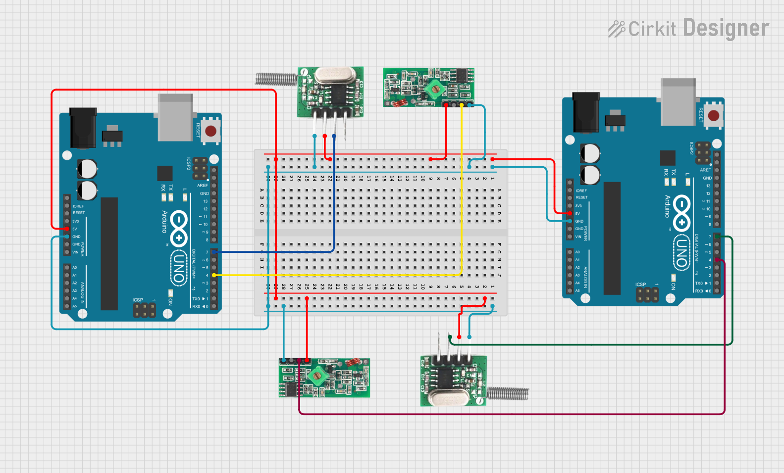
Circuit Documentation
Summary
This circuit involves two Arduino UNO microcontrollers, two RF 433 MHz Transmitters, and two 433 MHz RF Receiver Modules. The circuit is designed to facilitate wireless communication between the transmitters and receivers using the Arduino microcontrollers.
Component List
RF 433 MHz Transmitter
- Description: A wireless transmitter module operating at 433 MHz.
- Pins: -ve, Data, +ve
- Purpose: Transmits data wirelessly to the receiver module.
433 MHz RF Receiver Module
- Description: A wireless receiver module operating at 433 MHz.
- Pins: VCC, DATA, GND
- Purpose: Receives data wirelessly from the transmitter module.
Arduino UNO
- Description: A microcontroller board based on the ATmega328P.
- Pins: UNUSED, IOREF, Reset, 3.3V, 5V, GND, Vin, A0, A1, A2, A3, A4, A5, SCL, SDA, AREF, D13, D12, D11, D10, D9, D8, D7, D6, D5, D4, D3, D2, D1, D0
- Purpose: Controls the transmitter and receiver modules and processes the data.
Wiring Details
RF 433 MHz Transmitter 1
- Pin +ve: Connected to 5V on Arduino UNO 1 and Arduino UNO 2
- Pin -ve: Connected to GND on Arduino UNO 1 and Arduino UNO 2
- Pin Data: Connected to D7 on Arduino UNO 2
RF 433 MHz Transmitter 2
- Pin +ve: Connected to 5V on Arduino UNO 1 and Arduino UNO 2
- Pin -ve: Connected to GND on Arduino UNO 1 and Arduino UNO 2
- Pin Data: Connected to D7 on Arduino UNO 1
433 MHz RF Receiver Module 1
- Pin VCC: Connected to 5V on Arduino UNO 1 and Arduino UNO 2
- Pin GND: Connected to GND on Arduino UNO 1 and Arduino UNO 2
- Pin DATA: Connected to D4 on Arduino UNO 2
433 MHz RF Receiver Module 2
- Pin VCC: Connected to 5V on Arduino UNO 1 and Arduino UNO 2
- Pin GND: Connected to GND on Arduino UNO 1 and Arduino UNO 2
- Pin DATA: Connected to D4 on Arduino UNO 1
Arduino UNO 1
- Pin 5V: Connected to +ve on RF 433 MHz Transmitter 1, +ve on RF 433 MHz Transmitter 2, VCC on 433 MHz RF Receiver Module 1, and VCC on 433 MHz RF Receiver Module 2
- Pin GND: Connected to -ve on RF 433 MHz Transmitter 1, -ve on RF 433 MHz Transmitter 2, GND on 433 MHz RF Receiver Module 1, and GND on 433 MHz RF Receiver Module 2
- Pin D7: Connected to Data on RF 433 MHz Transmitter 2
- Pin D4: Connected to DATA on 433 MHz RF Receiver Module 2
Arduino UNO 2
- Pin 5V: Connected to +ve on RF 433 MHz Transmitter 1, +ve on RF 433 MHz Transmitter 2, VCC on 433 MHz RF Receiver Module 1, and VCC on 433 MHz RF Receiver Module 2
- Pin GND: Connected to -ve on RF 433 MHz Transmitter 1, -ve on RF 433 MHz Transmitter 2, GND on 433 MHz RF Receiver Module 1, and GND on 433 MHz RF Receiver Module 2
- Pin D7: Connected to Data on RF 433 MHz Transmitter 1
- Pin D4: Connected to DATA on 433 MHz RF Receiver Module 1
Documented Code
Arduino UNO 1 Code
void setup() {
  // put your setup code here, to run once:

}

void loop() {
  // put your main code here, to run repeatedly:

}
Arduino UNO 2 Code
void setup() {
  // put your setup code here, to run once:

}

void loop() {
  // put your main code here, to run repeatedly:

}